I’ve spent some more time looking at how the AY sound driver used by Tim Follin for the ZX Spectrum works and one thing I always wanted to do was to see if I could get it up and running on my RC2014 just so that, well, I’m not sure, but why not?
- Part 1 – Initial analysis and a look at the sound “op codes”
- Part 2 – Looking at the sound driver and player.
- Part 3 – Running everything on an RC2014.
The key thing that appeals to me about this over other chiptune players, is that this is the actual driver written by S Ruddy directly for Tim Follin to compose with. It is a complete sound specific “op code” language created to allow the sound chip to be programmed. Many chiptune players or trackers just sample the data being streamed to the sound device and stream that back. That makes for a nice, processor architecture independent playback, but what I’m hoping for here is to run the “sound interpreter” live and feed it the instructions for what to play, just like it would have been done in the original games.
When I took a detailed look at the harness used to run the driver though I could see it continually updated the Spectrum display by directly writing to its screen memory. This is essentially what prompted my desire for ZX Spectrum Compatible Video for RC2014 and its associated diversions into PIO on the Raspberry Pi Pico and Watching a Z80 from an RP2350, which I have recently made a lot of progress on.
So I believe I am now in a position to give things a go and at least work out what else I’ll need to do.
Equipment required:
- RC2014 of some sort. I’m using my Classic II.
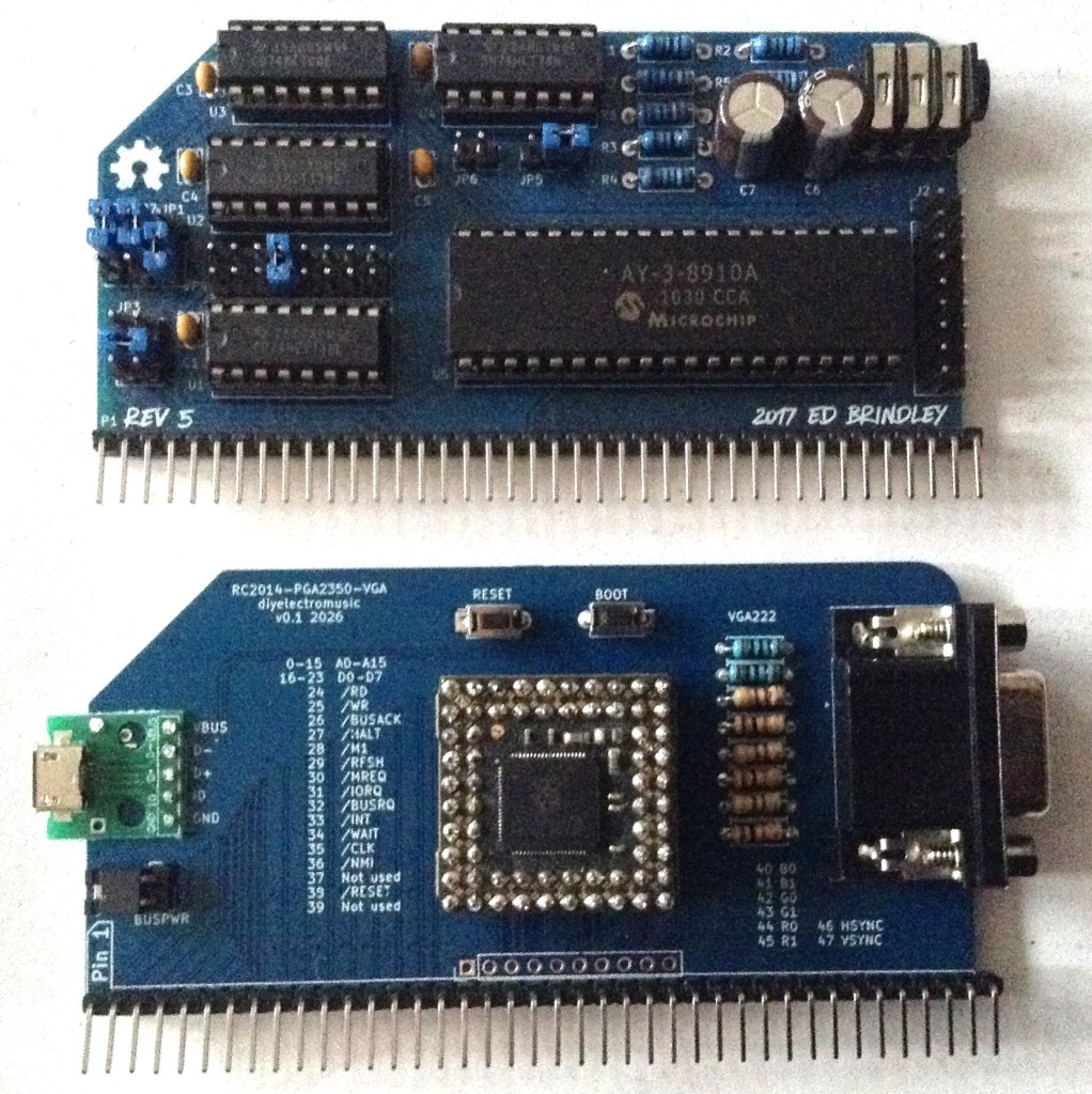
- AY-3-8910 RC2014 sound card. I’m using Ed Brindley’s “RC2014 YM/AY Sound Card” (I have V5 which is slightly different to the latest one), as I want to use a real AY device. But I’ll probably also give it a go with the “Why Em-Ulator Sound Module” too.
- My ZX Spectrum Compatible Video for RC2014 – Part 2 PCB.
- A VGA monitor and sound amplification of some sort.
Assembling and Loading
The files are part of the Follin archive set up by Dean Belfield and can be found here (there are more details in part 1): https://github.com/breakintoprogram/archive-follin/tree/main/Examples/AY/Ghouls%20n%20Ghosts
There are three assembler files which I’m combining into the following structure:
; From exec_g+gmusic.z80
Code_Start: EQU 40000 ; Where the AY driver is loaded
Data_Start: EQU 50000 ; Where the tunes are loaded

ORG Code_Start

EI		; This is required for some emulators

; ----------------------------
; then whole of aydrive.z80

; ----------------------------
; then whole of g+gmusic.z80
I’m using the online assembler once more: https://www.asm80.com/onepage/asmz80.html but this requires a couple of changes:
- All single operand “ADD n” instructions need expanding into “ADD A,n”.
- TUNES and EFFECTS from g+gmusic.z80 clash, so I renamed them to NTUNES and NEFFECTS as they specify the number of tunes and effects used at the start of the data block.
At this point the whole lot assembles and produces a HEX file and a listing. From the list file, we can see the key sections (40000 = 0x9C40; 50000=0xC350):
9C40                          .ORG   Code_Start
...skip...
B037                CODE_BOT:
B037                CALC1:    EQU   CODE_BOT-CODE_TOP
B037                          ;--------------------------------------
B037                CALC2:    EQU   50000
B037                TUNES:    EQU   50002
B037                EFFECTS:   EQU   50003
B037                          ;TUNES_A:        EQU 50004
B037                          ;TUNES_B:        EQU 50024
B037                          ;TUNES_C:        EQU 50044
B037                          ;FX_TAB:         EQU 50064
B037                          ; END
C350                          .ORG   Data_Start
C350                NTUNES:   EQU   5
C350                NEFFECTS:   EQU   21
C350                          ;--------------------------------------
C350   30 11                  DW   CALC
C352   05                     DB   NTUNES
C353   15                     DB   NEFFECTS
C354                          ;--------------------------------------
...skip...
D483   83                     DB   STOP
D484                          ;======================================
D484                CALC:     EQU   $-DATA_TOP
This will load into the RC2014 SCC monitor, but it won’t run yet. Well it will, but it won’t be doing anything useful.
As described in Part 2 this hooks into the ZX Spectrum ROM for the character definitions for the screen display.
The ZX Spectrum character set is stored in the following locations (details here):
3D00  (15616)   Character 32 "Space"
3D08  (15624)   Character 33 "!"
...
3D80  (15744)   Character 48 "0"
...
3DC8  (15816)   Character 57 "9"
...
3E08  (15880)   Character 65 "A"
...
3E30  (15920)   Character 70 "F"
...
3FFF  (16383)   Character 127 "(C)"
The locations for “0” to “9” and “A” through “F” are particularly significant, as they are bought out in the ROM_TAB which is used by the HEX routine to display hexadecimal numbers on the screen.
I need to copy all of this data out of an original 48K ROM image into memory somewhere.
.org 48000
ROM_Char_Tab:
db 0,0,0,0,0,0,0,0, 0,0,0,0,0,0,0,0, 0,0,0,0,0,0,0,0, 0,0,0,0,0,0,0,0
...
ROM_Num_Start:
db 00h,3Ch,46h,4Ah,52h,62h,3Ch,00h, 00h,18h,28h,08h,08h,08h,3Eh,00h
...
ROM_Hex_Start:
db 00h,3Ch,42h,42h,7Eh,42h,42h,00h
I’ve put this before the Code_Start and checked the listing file – there is nothing at address 48000.
Then the ROM_TAB itself gets replaced with the new addresses of the digits “0” to “9” (based on ROM_Num_Start) and letters “A” to “F” (based on ROM_Hex_Start).
Whilst I’m thinking about memory, the SCC monitor installation guide states this about the build for RC2014:
“Configuration R1 contains just the Small Computer Monitor and runs on all standard RC2014 kits (Mini, Classic, Plus and Pro). It fits in an 8k byte ROM which is mapped into memory from address $0000 to $1FFF. It requires RAM from $FD00 to $FFFF, leaving the rest free for the user. The ROM is not paged out of memory during operation.”
Taking the listing for the build and the above information, I’m working with the following memory map when loading this into the SCC monitor:
0000-1FFF  RC2014 8K ROM address space: Running the SCM.
4000-5AFF  Spectrum compatible screen memory area at 16384
8000-FFFF  RC2014 32K RAM address space. Split as follows:
  9C40-B034  AY Driver loaded at 40000
  BB80-BF80  ROM Character Table at 48000
  C350-D484  AY Tune data at 50000
  FD00-FFFF  SCM RAM data area
It looks like I might be able to duplicate the ROM character set at the same location of the ZX Spectrum – i.e. 3C00-3FFF, but that is not decoded by my RC2014 at present (I might be able to make a custom ROM for one of my other systems though).
At this point I can run the code and see something on the display which is great. But it still isn’t actually running yet.

So now the “porting” across to the RC2014 can begin in earnest.
Audio Output
The first thing to sort out is how to access the AY-3-8910 device. The ZX Spectrum has this sitting at IO port 0xFFFD to select a register for the device and 0xBFFD to provide it with data (details here).
By default the RC2014 AY sound cards use ports 0xD8 (register) and 0xD0 (data) (details here).
There is a short routine in the sound driver that outputs data to the sound device which will need updating:
;--------------------------------------
; This routine will send the contents
; of C to the AY register pointed to
; by A.

OUT_CA_AY:
;Speccy
   LD E,C
   ;LD BC,65533   ; Spectrum register
   LD BC,0d8h     ; RC2014 register
   OUT (C),A
   ;LD BC,49149   ; Spectrum data
   LD BC,0d0h     ; RC2014 data
   LD A,E
   OUT (C),A
   RET
There are a couple more references to 65533 and 49149 the two ZX Spectrum AY registers, so these will need updating too, although I think they are just there to turn everything off if the code exits from the main loop.
Main Update Loops
So back to the main code and why I’m not getting any updates.
The first culprit I can see is probably the HALT instruction at the start of the LOOP. Here is an annotated listing:
LOOP:
    HALT         ; Wait for 50Hz interrupt from ULA for sync
    CALL UPDATE  ; Update sound parameters
    LD A,2
    OUT (254),A  ; Set Border = 2 in ULA
    CALL REFRESH ; Update display
    XOR A
    OUT (254),A  ; Set Border = 0 in ULA
    CALL CLOCK
    CALL KEYSCAN ; Process last key pressed
    LD A,07FH
    IN A,(254)   ; Read keyboard from ULA
    AND 1        ; Keep going unless SPACE is pressed
    JP NZ,LOOP
    LD BC,65533  ; Turn off AY sound
    LD A,7
    OUT (C),A
    LD BC,49149
    LD A,63
    OUT (C),A

    POP HL       ; Tidy up and stop
    POP DE
    POP BC
    POP AF
    RET
Processor HALT
In Z80 assembler, HALT is defined as follows:
“The HALT instruction suspends CPU operation until a interrupt or reset is received. While in the halted state, the processor will execute NOP’s to maintain memory refresh logic.”
I gather this is being used here to synchronise the update with something like the display code from the ULA. The driver is assumed to run at 50Hz, but at the moment I’m not sure what is triggering that.
In fact, those OUT and IN statements are a clue – port 254 (0xFE) is the ULA. So this loop is waiting to be kicked into action by the ULA and then pokes the ULA back and then reads back from it before deciding what to do next.
There is a really good reference here for the ULA port (see Hardware, Port 0xFE): https://worldofspectrum.org/faq/reference/48kreference.htm
Apparently reading from port 0xFE will also effectively trigger a HALT too as everything has to wait for the ULA to respond to the read.
Keyboard Handling
The following code is checking for the space key and will drop out of the loop if pressed:
LD A,07FH
    IN A,(254)   ; Read keyboard from ULA
    AND 1        ; Keep going unless SPACE is pressed
    JP NZ,LOOP
Bit 0 of address 0x7FFE is the SPACE key. There is a quirk in how the Z80 does port IO. It uses the contents of the A register as the high byte of a 16-bit port address, hence loading it here with 0x7F and then reading from port 254 (0xFE) as the low byte. This results in an IORQ going out for port 0x7FFE which the ULA will respond to. Details of how the ULA scans the keyboard can be found here: https://sinclair.wiki.zxnet.co.uk/wiki/ZX_Spectrum_ULA
Prior to this, the KEYSCAN routine looks for keypresses that will control the tune player. Looking through the code, I think it is doing the following (annotations are my interpretations):
KEYSCAN:        LD A,(ASCII)   ; ASCII=23560(5C08), System Var LAST-K
                OR A           ; Return straight away if 0
                RET Z
KEYSCAN1:       CP 32          ; Jump to KEYSCAN2 if >= 32 (space)
                JR NC,KEYSCAN2
                CP 8           ; 8 = Cursor LEFT
                JP Z,KEYwait   ; Think this slows it down?
                CP 9           ; 9 = Cursor RIGHT
                JP Z,KEYfast   ; Think this speeds it up (FF)?
                CP 13          ; 13(D) = ENTER
                JR NZ,GOout
                CALL TUNEOFF   ; Enter stops the tune
                LD A,6
                OUT (254),A
                JR GOout       ; END
KEYSCAN2:       CP 48
                JR C,GOout     ; <"0" END
                CP 58
                JR NC,DOeffect ; >"9" jump to Doeffect
                AND 15         ; 0-9 is a tune to play
                LD E,A
                LD A,(Tunes)   ; Tunes = Number of tunes
                CP E
                JR Z,GOout
                JR C,GOout
                LD A,E         ; Valid tune to play
                PUSH AF
                LD DE,408FH    ; Update display
                CALL HEX
                POP AF
                CALL TUNE      ; Start the tune in A
                LD HL,0
                LD (MINS),HL
                JR GOout       ; END
DOeffect:       CP 61H
                JR C,GOout     ; <"a" END
                CP 61H+26
                JR NC,GOout    ; >="z" END
                SUB 061H       ; A = 0 to 25
                LD E,A
                LD A,(Effects) ; Effects = Number of effects
                CP E
                JR Z,GOout
                JR C,GOout
                LD A,E
                PUSH AF
                LD DE,4087H    ; Update display
                CALL HEX
                POP AF
                CALL FX        ; Play the effect in A
                               ; END
GOout:          XOR A
                LD (ASCII),A   ; Clear LAST-K
                RET

KEYwait:        LD HL,ASCII
                LD (HL),0      ; Clear LAST-K?
                LD B,20
KEYloop:        HALT           ; Wait for 50Hz sync
                DJNZ KEYloop   ; and do it 20 times
                RET

KEYfast:        LD B,50
KEYloop2:       PUSH BC
                CALL REFRESH   ; Update AY tune parameters
                CALL CLOCK     ; Update clock
                POP BC
                DJNZ KEYloop2  ; and do it 50 times without waiting
                JR GOout
So in summary, I believe the keys are:
- LEFT – slow down playback
- RIGHT – skip forward playback
- ENTER – stop playing
- 0-9 – select a tune and start playing it
- a-z – select an effect and start playing it
I can’t monitor the keyboard at the same speed as the original, as I’ve only got a serial port to go with. But I can make it automatically play a tune by presetting what it believes is a keypress to “0” (and making sure the code doesn’t clear it on startup). Note that the location for LAST-K (0x5C08, 23560) is being accessed, but I don’t have comparable function here so I need to redirect it by changing the value for ASCII.
LASTK:
db 48  ; Preset keypress to "0" for the first tune

;ASCII:          EQU 23560
ASCII:          EQU LASTK
The following video shows everything updating but with no real concept of time synchronisation – this is simply free-running at this point.
50 Hz Interrupt
As previously mentioned the HALT instruction is acting as a synchronisation signal. From the details of the design of the ULA, we find that the /INT signal is generated in part off the VSync signal with some additional logic to ensure the length of the pulse is long enough, but not too long, for the Z80 to respond.
This prompted a bit of a diversion to figure out quite how to get something running on the RC2014 to help all the timing. In the end I settled on a logic circuit driven from a 1.8432MHz crystal that gave me the requisite 50Hz interrupt. After a bit more fiddling with the SCC monitor code, I was able to get the Z80 responding to the interrupt as required and thus enabling the HALT to do its job!
Full details on how that works can be found here: https://emalliab.wordpress.com/2026/08/26/rc2014-50-hz-interrupt-source/
Final Loading Sequence
So I now have the following steps:
- Take my RC2014 and install the AY or Why-Em card and my Spectrum Video card.
- Boot into the SCC monitor.
- Initialise the 50Hz timer interrupt hardware and SCC monitor as described here but DO NOT CONNECT THE INTERRUPT SOURCE (yet).
- Load in the hex file as described above.
- Run the sound driver using “g 9c40”.
- Plug in the interrupt source and watch it all kick off.
The result can be seen below.
This has been a long while in the making. I first had this thought over a year ago and it has required a lot of pieces coming together to make it happen:
- Meeting Dean at RetroFest 2025 and talking about the Follin archive, spawning the thought in the first place.
- Finding out about the AY-3-8910/8912:
- Arduino and AY-3-8910 (and subsequent posts)
- AY-3-8910 Experimenter PCB Design
- Arduino AY-3-8910 Shield Design
- Finding out how the sound driver works
- Working out how to get code running on the RC2014
- To get Spectrum-like video working on the RC2014:
- Digging into the RP2040/RP2350 PIO:
- Using RP2350 to watch the Z80 bus:
- Looking at how RP2350 does VGA:
- Tying RP2350 VGA to the ZX Spectrum display:
- Getting the AY Driver running on RC2014 with the Video card:
- Update: Creating a ROM version of the code:
But now that it has, I’m really, really pleased to finally hear that tune.
Kevin


