Having spent a fair bit of time over on my other blog looking at ZX Spectrums, I thought it about time I dragged some of that over here and looked at music making 1980s computer style.
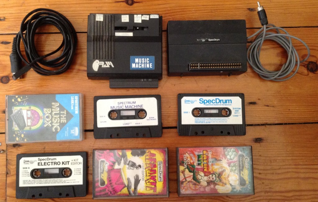
This shows everything I had back in the day for my ZX Spectrum. The hardware (from left to right): a 128K MIDI lead (5 pin DIN to BT RJ style plug); the RAM Music Machine; and a SpecDrum.
The tapes (top left to bottom right): Melbourne House’s The Music Box (for 48K and 128K Spectrum); the RAM Music Machine software; the SpecDrum software. Then on the bottom row the three additional drum kits for the SpecDrum: Electro, Afro and Latin.
There are a lots of resources online about all of these devices, but the one-line summary of each is as follows:
- 128K MIDI Lead: The Spectrum 128 had a keypad/MIDI socket which hangs off the additional general purpose IO pins from the AY-3-8912 sound chip.
- RAM Music Machine: From 1986 this provides MIDI IN, OUT and THRU as well as sample playing at 19.4kHz.
- Cheetah SpecDrum: From 1985 this is essentially a DAC with drum machine software, additional kit samples and a drum kit editor to combine samples into a custom kit. Whilst supporting 8 samples, only 3 can be played at the same time.
For this first post, I’m taking a bit of a dive into the default MIDI support that appeared with the original Spectrum 128K “Toastrack”.
I started with a Spectrum+ but soon upgraded to an original 128K, so this is where I spent most of my own Spectrum days. I still have my original 128K, but I need to give it a bit of TLC – at least a new keyboard membrane – before I can get it out again.
128K Spectrum and MIDI
There were three major advances (at least as far as I was concerned) with the new 128K Spectrum when it came out: more memory, of course; the AY-3-8912 sound chip (the slightly smaller version of the AY-3-8910); and the prospect of MIDI.
It wasn’t full MIDI, that still required some additional peripherals, but with the correct lead, it was possible to use the ZX Spectrum to control a MIDI synthesizer via MIDI OUT.
It turns out that lead is a curious beast though – the Spectrum’s implementation of MIDI isn’t following the MIDI spec as such. There are a few resources that discuss what is going on:
- https://oldmachinery.blogspot.com/2012/11/spectrum-128-and-midi.html
- https://www.benophetinternet.nl/hobby/vanmezelf/ZX_Spectrum_Midi_Out.pdf
- https://s-huehn.de/spectrum/en/hardware2.htm#zx128midi
- https://sinclair.wiki.zxnet.co.uk/wiki/AY-3-8912
But apart from the odd plug, it is a variant of BT style 6-pin “phone” plug that these days is particularly hard to come by, looking at the schematic for the 128K we can see a bit more what is going on:
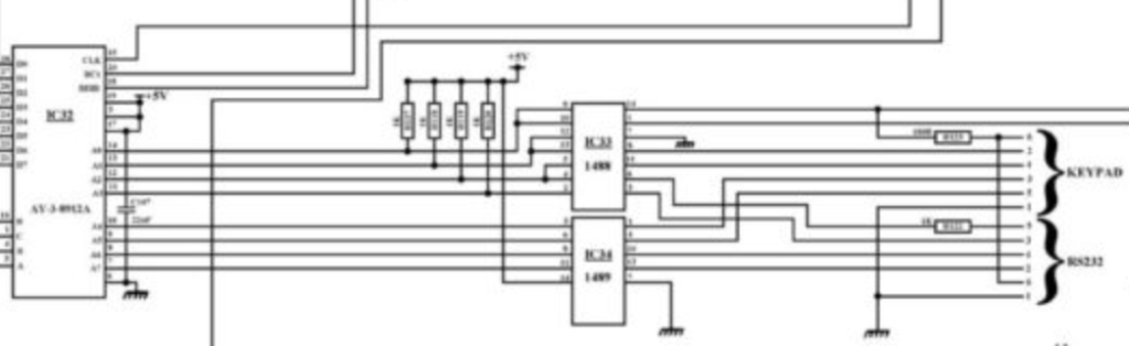
It isn’t very easy to make out, but the chip on the left is the AY-3-8912 and the two chips in the middle are RS232 driver/receiver chips. They are hanging off the AY-3-8912’s IO port and we can see in the 128K Service Manual what the 8 bits of this port are used for:
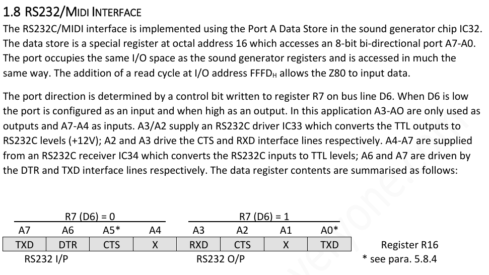
R16 is the (octal) register 16 (i.e. 14 in decimal) of the AY-3-8912, which corresponds to IO PORT A. R17 would be PORT B, but there is no PORT B on the 8912, that only exists on the 8910.
To see how this is used for MIDI, we can refer to the 128K Spectrum ROM Dissassembly:
; ------------------------
; Send Byte to MIDI Device
; ------------------------
; This routine sends a byte to the MIDI port. MIDI devices communicate at 31250 baud,
; although this routine actually generates a baud rate of 31388, which is within the 1%
; tolerance supported by MIDI devices.
; Entry: A=Byte to send.

L11A3:  LD   L,A          ; Store the byte to send.

        LD   BC,$FFFD     ;
        LD   A,$0E        ;
        OUT  (C),A        ; Select register 14 - I/O port.

        LD   BC,$BFFD     ;
        LD   A,$FA        ; Set RS232 'RXD' transmit line to 0.
                          ; (Keep KEYPAD 'CTS' output line low to prevent the keypad resetting)
        OUT  (C),A        ; Send out the START bit.

        LD   E,$03        ; (7) Introduce delays such that the next bit is output 113
                          ;     T-states from now.

L11B4:  DEC  E            ; (4)
        JR   NZ,L11B4     ; (12/7)

        NOP               ; (4)
        NOP               ; (4)
        NOP               ; (4)
        NOP               ; (4)

        LD   A,L          ; (4) Retrieve the byte to send.

        LD   D,$08        ; (7) There are 8 bits to send.

L11BE:  RRA               ; (4) Rotate the next bit to send into the carry.
        LD   L,A          ; (4) Store the remaining bits.
        JP   NC,L11C9     ; (10) Jump if it is a 0 bit.

        LD   A,$FE        ; (7) Set RS232 'RXD' transmit line to 1.
                          ;     (Keep KEYPAD 'CTS' output line low to prevent the keypad resetting)
        OUT  (C),A        ; (11)
        JR   L11CF        ; (12) Jump forward to process the next bit.

L11C9:  LD   A,$FA        ; (7) Set RS232 'RXD' transmit line to 0.
                          ;     (Keep KEYPAD 'CTS' output line low to prevent the keypad resetting)
        OUT  (C),A        ; (11)
        JR   L11CF        ; (12) Jump forward to process the next bit.
There is more, but this is enough to see how MIDI is encoded as follows:
PORT A Value:
$FA -> 1111 1010 -> transmit line to 0
$FE -> 1111 1110 -> transmit line to 1
This is toggling the AY’s PORT A A2 bit according to the register usage, which maps over onto the RS232 CTS line.
The above schematic extract has been redrawn by others which makes things a bit easier to see what happens next:
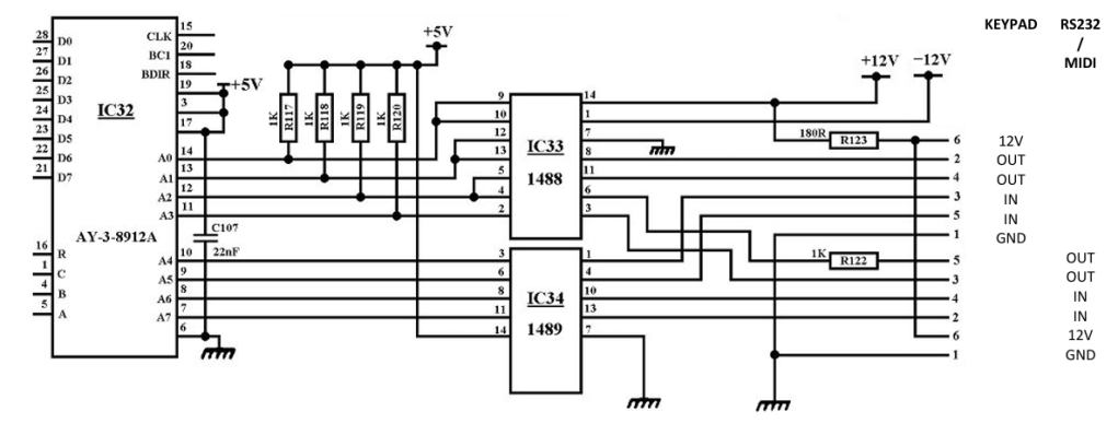
A2 from the AY chip goes to IC33 which is a MC1488 quad line driver. It is powered from 12V and -12V and generates the RS232 voltages required. RS232 requires a positive and negative voltage with respect to a common ground. For the MC1488 it specifies that for a VCC of +/-13V it generates a high and low voltage output of +/- 9-10.5V.
From the datasheet, we can see that the inputs get inverted:
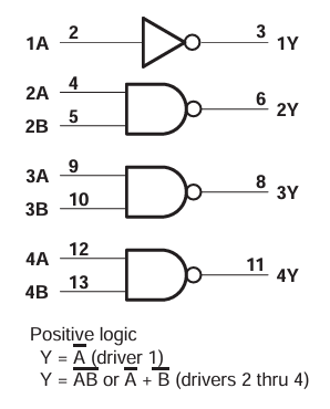
The AY A2 pin goes to pins 4 and 5, and thus pin 6 is the output which goes via a 1K resistor to pin 5 of the MIDI/RS232 socket.
Unfortunately, the pin numbering for those sockets as listed above (and in the linked document) seem opposite to those used with BT phone sockets (at least I think – it is very confusing trying to figure out which pin is which on the plugs and sockets). The references for telephony I’ve found have pin 1 as the pin nearest the locking latch, but in the above link (and I believe in the schematic above) pin 6 is the one nearest to the locking latch.
Looking inside my 128K MIDI cable, and checking for continuity, I can see the following:
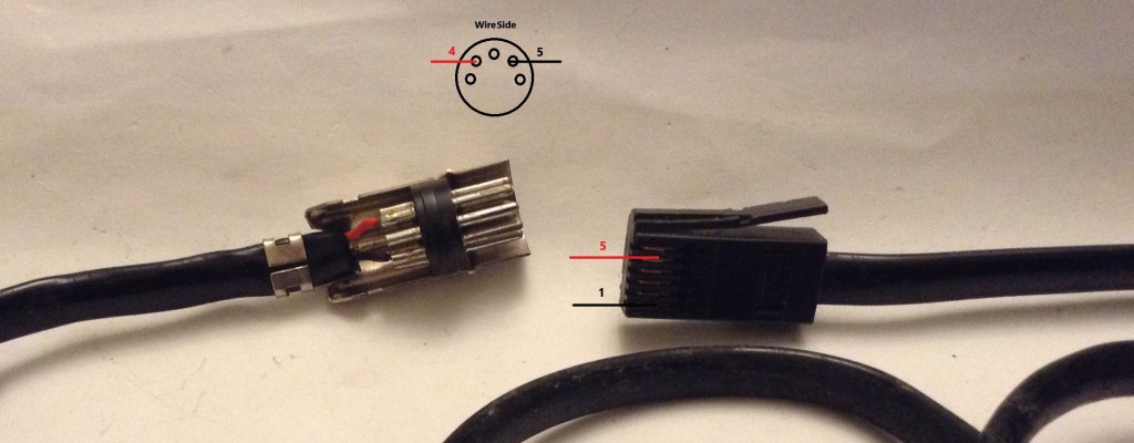
MIDI pin 4 (the VCC/source connection usually) seems to be connected to BT pin 5 which is RS232 CTS. MIDI pin 5 (the TX/sink connection usually) seems to be connected to BT pin 1 which is GND.
Another consequence of this wiring is that there is no grounded shield in the cable. With MIDI pin 2 is usually connected to ground, but only at the transmit side. With this cable pin 2 is left unconnected at both ends.
Normally with MIDI, when VCC and TX are HIGH (transmitting a “1”), no current flows. But when TX is pulled LOW (for a “0”) it allows a 5mA current loop to flow through an optoisolator, reproducing the signal in an electrically isolated way in the receiving equipment. The best explanation of how MIDI works in my view is this video: https://www.youtube.com/watch?v=0L7WAMFWSgY
With the Spectrum circuit, it would appear that the default position is now for what was VCC (now CTS) and TX (now GND) both to be LOW (for a “0”) so no current flows. Actually, as this is generated by the MC1488, we don’t get a “zero” condition, we get a negative voltage condition for LOW. This means that the protection diode in the receiving MIDI circuit will kick in as “VCC” (CTS) is more negative than “TX” (GND) and so it will conduct. The optoisolator will remain off though regardless.
So when CTS goes HIGH (for a “1”) it allows current to flow, but how much current?
Assuming the 12V through the RS232 line driver (in reality output is slightly less than VCC), and a typical MIDI receiving circuit (so maybe a ~1.5V Vf for the optoisolator and two 220R resistors as per the MIDI spec) we have a current of:
- I = (12 – 1.5) / (1000 + 180 + 220 + 200) =~ 6mA.
So I guess, although this seems to work somewhat in reverse to a normal MIDI circuit, it would still work fine for any MIDI receiving equipment that is following the MIDI Spec.
If it was ever plugged into something that had a non-standard MIDI IN port though – for example, if they skimmed on the opto-isolator or the protection diode, then the receiver may find itself on the wrong end of the Spectrum’s 12V line or even worse, with -12V with respect to GND, which I imagine wouldn’t end well.
For this reason, the aforementioned document recommends building a simple transistor circuit to “correct” the Spectrum’s MIDI OUT to make it more aligned to the official MIDI spec.
So in summary, the full sequence from assembler to MIDI signals is as follows:
A2=0 -> CTS = 1 -> +12V (ish) -> Current loop flows -> MIDI "0" received
A2=1 -> CTS = 0 -> -12V (ish) -> Current loop stops -> MIDI "1" received
Notice how that whilst A2 corresponds directly to a MIDI “0” or “1” being transmitted, anyone monitoring the hardware MIDI signal will see the CTS signal taking the opposite state due to the fact that the Spectrum’s MIDI link is GND based not VCC based.
Goodness knows what anyone would think if they measured the negative state…
Conclusion
Having worked through all this, I’m now looking back with moderate concern at the free abandon of plugging my ZX Spectrum into my treasured Casio CZ3000 back in the day. I was blissfully ignorant of the above, and just had fun programming my synth via the Spectrum’s BASIC MIDI commands. But as far as I know we all survived the experience and so I hope to reunite them one day.
But I am now seriously considering some electronics to do things properly. I have a few options;
- The aforementioned transistor fix for the 128K as it stands, which I will probably try. It would be good to come back to this post with some oscilloscope traces once I get things up and running.
- Getting my RAM Music Machine going.
- Building a DIY MIDI interface. Two really interesting candidates are:
Kevin


