I’m wanting to do some experimenting with the Pimoroni PGA2350 which is a really neat, 25x25mm, RP2350 board with all 48 GPIO pins of the larger RP2350B bought out to two rows arranged in a square. But it isn’t very breadboard friendly.
More recently there are now DIP based breakouts that also support the RP2350B and all 48 GPIO, but eventually I’d like to use a RP2350B in a design of my own and the PGA2350 is such a good form factor to use for that. I’m not ready to attempt a SMD design using a bare RP2350 itself just yet.
So I had a need to be able to experiment with a PGA2350 and hence decided to create this simple breakout board.
Warning: There is a Waveshare RP2350 module (the Waveshare Core 2350B) in the same form factor, but this MUST NOT BE USED. The pinouts are slightly different but most significantly, some of the power and GND overlap with GPIO on the Pimoroni board. I might re-spin a version of this board for the Waveshare at some point…
Warning! I strongly recommend using old or second hand equipment for your experiments. I am not responsible for any damage to expensive instruments!
If you are new to electronics and microcontrollers, see the Getting Started pages.
The Circuit
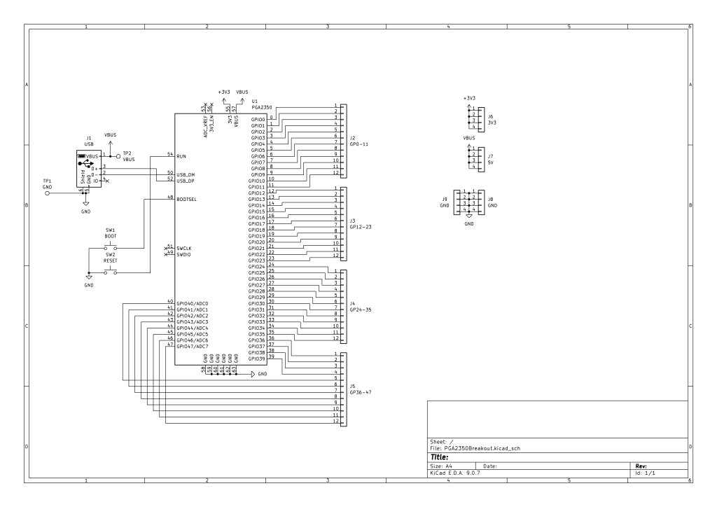
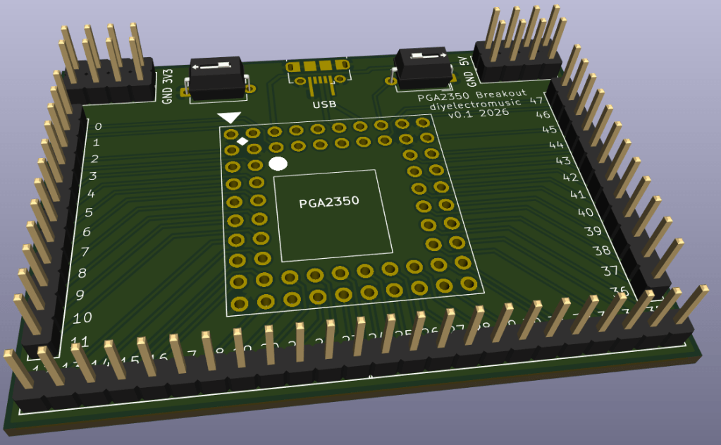
There is little more than the PGA2350 and some headers. There just a USB socket for communications and power, and buttons for BOOT and RESET.
I had to create my own KiCAD symbol for the PGA2350 however, but it is very similar to the symbol for the RP2350 itself.
I’ve also included some additional headers for GND, 3V3 and 5V (hanging off VBUS).
PCB Design
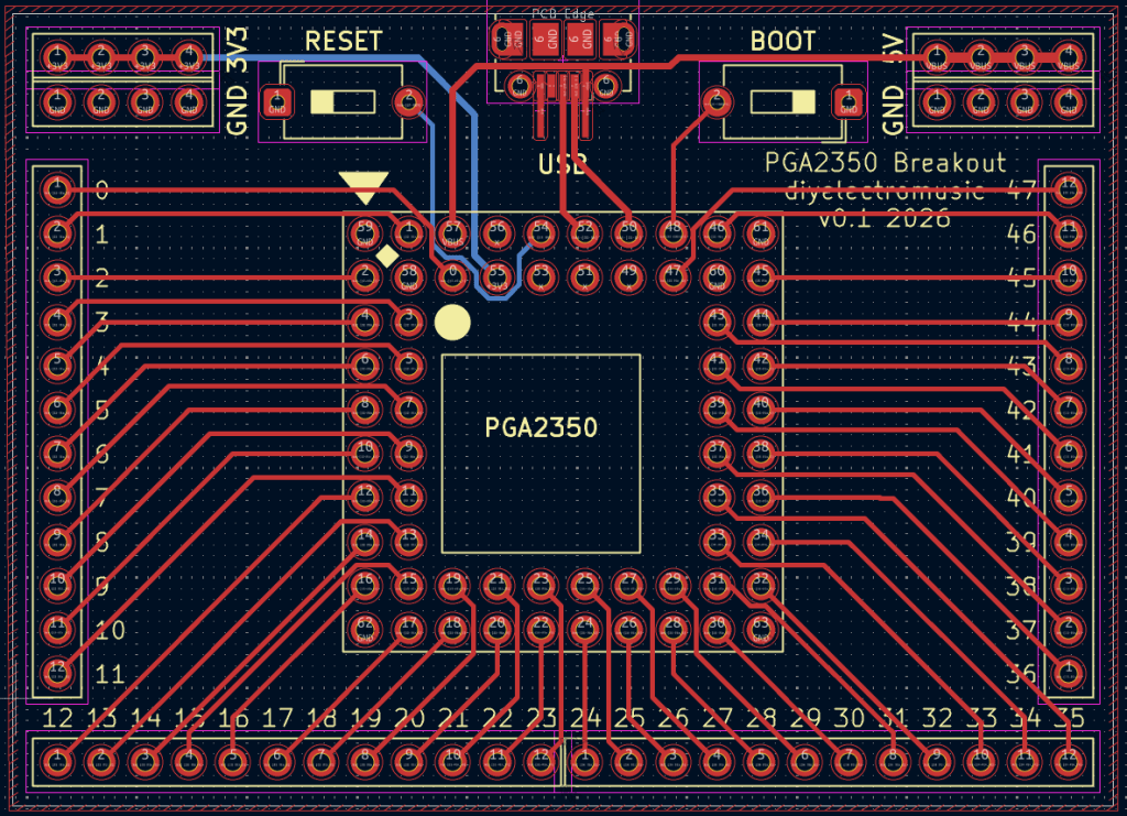
I’ve used the micro-USB socket footprint I’ve used in the past. I did think about using a micro-USB breakout board to make soldering easier, but wanted it to look a bit neater than that.
I also had to create a PGA2350 footprint to go with my symbol, but that wasn’t too difficult. Essentially setting the grid size to 2.54mm and keep adding pins. Numbering them took a while as I wanted the pin numbers to match the GPIO numbers as far as possible. There was probably an easier way to do this in KiCAD, but I often just work within what I know.
Then I added silkscreen GPIO numbers to all the breakout pin headers to make it easier to use.
I choose simple button footprints that I thought would match the two-pin buttons I have (spoiler: they didn’t. I had to bodge something together, but I’ll come to that when I write up the build guide).
Closing Thoughts
Pimoroni were selling pins and sockets in the PGA format, but they are now end-of-life. I’ve also found some 10×10, 68-pin PGA sockets (there are four additional pins, one on each inside corner) which I did wonder about using, but in the end I opted for a simpler footprint and will use dual-row, round pin, pin header sockets to mount the PGA2350.
I’m pretty sure that will work out ok.
Kevin
