This continues my series looking at hardware emulation of the AY-3-8912/8910:
- Part 1: Introduces the AVR-AY projects and available boards and how they go about using an AVR microcontroller, usually an ATMega48, to emulate an AY-3-8910 device. It walks through the functionality of the provided firmware.
- Part 2: My own experimenter PCB based on an overclocked (27MHz) ATMega328P. Unfortunately, when I left things, it wasn’t working.
This post picks up with an attempt to rebuild the firmware from source in an attempt to figure out what is going on.
Spoilers: At the end of it, it still doesn’t work though…
Warning! I strongly recommend using old or second hand equipment for your experiments. I am not responsible for any damage to expensive instruments!
ICSP Header
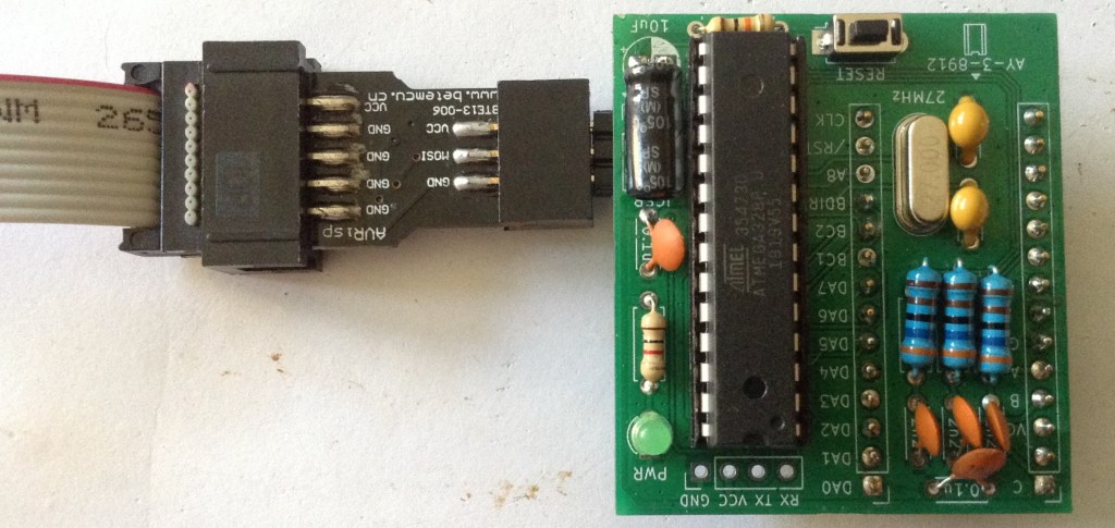
The first thing to do is to add the ICSP header to my AVR-AY. Unfortunately, as I mentioned in Part 2 I got the pinout back to front. But this can be easily accounted for by soldering the ICSP header onto the underside of the board.
I decided this would work best with a right-angled 2×3 pin header, which also means it sits nicely under the bent-over capacitor.
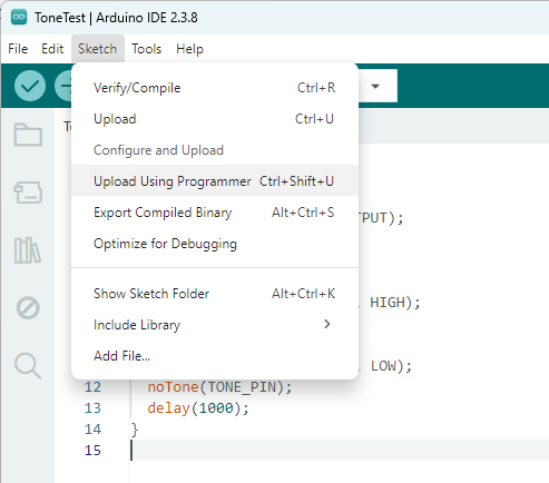
An easy check is to use the Arduino environment to download a blink sketch. As I’m using my USBasp again, I need to select that under “Tools” -> “Programmer”, then it is possible to use “Upload using Programmer” to load a sketch. This can be found under “Sketch” or as shown below, using the shortcut CTRL-SHIFT-U.
All being well, pin 13 should be toggling on and off, albeit at a slighter faster rate than expected – this is running off a 27MHz crystal rather than a 16MHz of course.
Note: LED_BUILTIN = D13 = PB5 = BC2 = ICSP CLK on this board, so that is fairly easy to probe with a scope, or even temporarily add in LED.
AVR Development
In every other case, I’ve never bothered to get into raw AVR development. I’ve found I can do everything I’ve been interested in doing via the Arduino environment.
Unfortunately one thing the Arduino environment won’t do is assembly. Plus it will always add in some bootstrapping code prior to running your setup() routine and it has some housekeeping code inbetween each call to the Arduino loop().
There are a number of options for including some assembler in an Arduino sketch, but it is quite limited and doesn’t scale to an entire program.
One option is to assemble it outside of the Arduino environment and then include it in the final build. But that is all a bit of a faff, so I’m dropping back to a non-Arduino build envirnment, and traditionally that meant using Atmel Studio.
But this is no more. When Microchip acquired Atmel in 2016, this was renamed Microchip Studio. But even that is now deprecated for new designs. But it is still available, so I’m starting with that.
Another option is winavr. I might return to giving this a try later…
LED Flash in Microchip Studio
To check everything is running with Microchip Studio, I opened one of the example projects, filtering for ATmega328, “megaAVR led example – ATmega328P Xplained MINI”. I think this is for one of their own dev boards.
This gives me a whole pile of code, but the only bit I’m interested in is in src/mega_led_example.c. Everything else in src/ASF and src/config I think is related to the dev board and examples, which I’ve mostly ignored.
I changed the provided code, which would flash an LED on a button press, to the following:
#define F_CPU 27000000UL

#include <asf.h>
#include <util/delay.h>

int main (void)
{
	/* set board io port */
	board_init();
	bool button_state = false;
	while(1){
		_delay_ms(1000);
		if(button_state){
			LED_Off(LED0);
			button_state = true;
		}else{
			LED_On(LED0);
			button_state = false;
		}
	}
}
LED0 and LED_On/Off are defined for the board, and in this case map onto PB5 which is the same as LED_BUILTIN being D13 for an Arduino Uno.
I first played save with F_CPU = 16MHz, but actually once everything was up and running, it seemed quite happy for me to set it to 27MHz for the delay to be accurate.
So, this now builds, but now to download it…
Microchip Studio and USBasp
There are a number of programmers supported within Microchip Studio, but USBasp isn’t one of them. To be able to use it, it has to be added as an external tool.
But before that can happen, you have to make sure you’re in Advanced Mode.
When installing, there is an option of running in Standard or Advanced mode. I choose standard, and consequently couldn’t find most of the things being talked about online in conjunction with USBasp and Microchip/Atmel Studio!
Once changed to Advanced Mode, under “Tools” there is an option for “External Tools”. Once selected, a new tool setup is entered for USBasp.
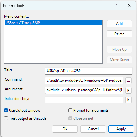
This has to use the same avrdude setup as described in Part 2, but the filename has to link into the paths that Microchip Studio will use.
- Title: anything you wish
- Command: path\to\avrdude.exe
- Arguments: avrdude -c usbasp -p atmega328p -U flash:w:$(ProjectDir)\Debug\$(TargetName).hex:i
Everything else is left as you see it above. When saved, there is now a new entry under “Tools” which can be used to download directly via USBasp.
Note: debugging is not possible, so the whole “Debug” set of menus is ignored.
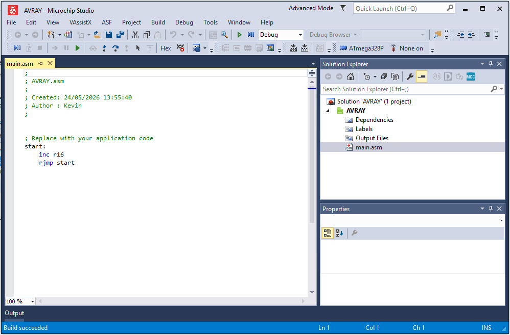
At this point I can use “Build” -> “Build Solution” and then “Tools” -> “USBasp-ATmega328P” to build code and get it running.
Microchip Studio Raw Assembler
Now onto the main reason for doing all this – can I build and run the assembler for the AVRAY?
Turns out that is one of the supported options. On creating a new project (curiously, for a C/C++ project there is an option to import an Arduino sketch), choosing assembler gives:
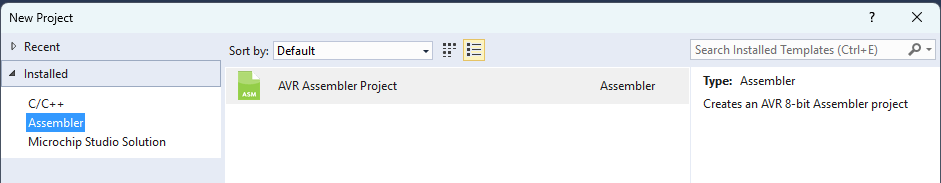
Then I’m asked to choose a MCU, so select ATmega328P and then I am provided with the following:
But actually when I went to get the source, there is already an Atmel Studio project file included (this is the source from: https://github.com/Yevgeniy-Olexandrenko/avr-ay-board/tree/main/firmware/v1.0/sources
On opening this project file, it requires the downloading of an additional pack: Atmega_DFP. I told it to download the specific version requested. But it seems to have ignored me and downloaded the latest one.
In the project properties I had to change the device from ATmega48PA to ATmega328P.
In order to avoid the need for an EEPROM configuration file (which requires the command line avrdude command as described in Part 2) I fixed the code to always assume no serial interface, always parallel interface, and 27MHz operation:
RESET:
; all existing setup code until...

    ; get byte 0 from EEPROM, check value > 0 or skip USART initialization if value = 0
    OutReg  EEARH, C00              ; is absent in Atmega48
    OutReg  EEARL, C00
    sbi     EECR, b0
    InReg   r16, EEDR
    cp      r16, C00
    ;breq    NO_USART
    jmp     NO_USART    ; Always jump to NO_USART

; More code
; In init Timer0

    ; 219512 Hz internal update clock
    ldi     r16, (27000000 / (1750000 / 8) - 1)
    out     OCR0A, r16
;    OutReg  EEARL, YH               ; set EEPROM address 2
;    sbi     EECR, b0
;    InReg   r18, EEDR               ; load byte 2 from EEPROM to r18
;    OutReg  OCR0A, r18              ; set PWM speed from byte 2 of EEPROM (affect AY chip frequency)


; After init Timer2

    ; check for parallel interface enabled in byte 1 of EEPROM
    OutReg  EEARL, ZH
    sbi     EECR, b0
    InReg   r16, EEDR
    cp      r16, C00
    ;breq    NO_EXT_INT    ; Never jump over the parallel init code
Then I used PD1 as a debug OUTPUT pin rather than its usual TX function. Whenever this was required, the following code would be used to set or clear the OUTPUT:
; Set
sbi   DDRD, b1
sbi   PORTD, b1

; Clear
sbi   DDRD, b1
cbi   PORTD, b1
Using this at the start of the MAIN_LOOP, then for ISR_INT0 and ISR_INT1, I can see that when I manually trigger BC1 or BDIR that the interrupt routines are indeed being called as required. There are two return points in each ISR. They basically have the following structure:
ISR_INT0: Triggered on BC1
   IF BDIR also HIGH jump to LATCH_ADDRESS
   Handle register read
   return from Interrupt

ISR_INT1: Triggered on BDIR
   IF BC1 also HIGH jump to LATCH_ADDRESS
   Handle register write
   return from Interrupt

LATCH_ADDRESS:
   Store register address
   return from Interrupt
I can also see that the main loop does utilise most of the CPU time between the PWM sample period.
Note: When looking at pins PB1-PB3 directly (i.e. before the filter circuit) I can see the PWM short pulses occuring, so I know all register initialisation for PWM is happening correctly too.
A note on initialising the interrupts:
    ; --------------------------------------------------------------------------
    ; Init external interrupts INT0 and INT1
    ; --------------------------------------------------------------------------
    ldi     r16, 0x0F               ; fallen edge of INT0, INT1
    OutReg  EICRA, r16
    ldi     r16, 0x03
    OutReg  EIFR, r16
    OutReg  EIMSK, r16
NO_EXT_INT:
The comment states “fallen edge” but the value 0x0F written to EICRA will set up the interrupts on the rising edge. Given that comments elsewhere in the ISRs discuss waiting for the signals to clear, I believe rising edge is correct.
For example, in ISR_INT0, triggered on a rising BC1, it will then wait for BC1 to clear before returning.
At this point, I’m throwing all timings to the wind and adding instructions to instrument the interrupt routines as follows:
ISR_INT0: Triggered on BC1
   PD0 = HIGH
   IF BDIR also HIGH jump to LATCH_ADDRESS
   Handle register read
   jump to CLEAR

ISR_INT1: Triggered on BDIR
   PD1 = HIGH
   IF BC1 also HIGH jump to LATCH_ADDRESS
   Handle register write
   jump to CLEAR

LATCH_ADDRESS:
   PD0 = PD1 = HIGH
   Store register address
   PD0 = PD1 = LOW
   return from Interrupt
The idea is to attempt to capture what the AVRAY thinks is going on with respect to BC1/BDIR. Here is a trace of the first access.
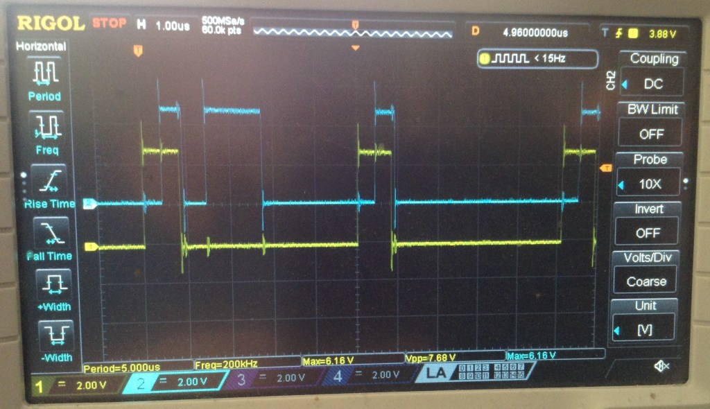
Yellow is PD0/BC1 and blue is PD1/BDIR. We can see PD0 going HIGH, hence an INT0 indicating BC1 was detected, followed by PD1 going HIGH which means INT0 has jumped to LATCH_ADDRESS, followed by both going LOW showing it is complete and the return from interrupt.
Then we see BDIR going high with no signal for BC1, so this means INT1 has triggered and a register write is occurring.
Then we see the LATCH_ADDRESS pattern repeat. In fact, including the first one, this repeats 10 times, which corresponds to my test code attempting to initialise 10 registers on startup.
But although the test code is using the same algorithm to latch the address (BC1=BDIR=HIGH) and then a register write (BC1=LOW, BDIR=HIGH) the emulator code isn’t “seeing” any more register writes.
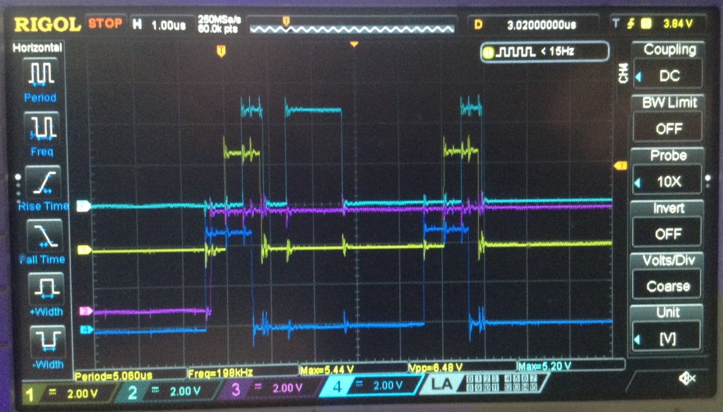
It turns out that the first write is the only one seen by the emulator at all. In the following trace, we can see the ten initialisation writes happening, then a short pause as the Arduino returns from the setup() code and starts the main loop(). Then there is regular scanning of a single AY register in the Arduino’s loop. The first trigger is the only one that shows the write happening at all.
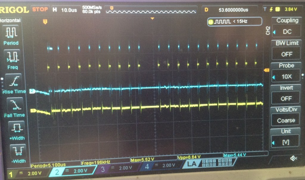
So to me, this implies that INT1 has somehow stopped functioning. I need to add in the traces of the actual BC1 and BDIR signals to be sure they are still happening though, although I see no reason to think they won’t be.
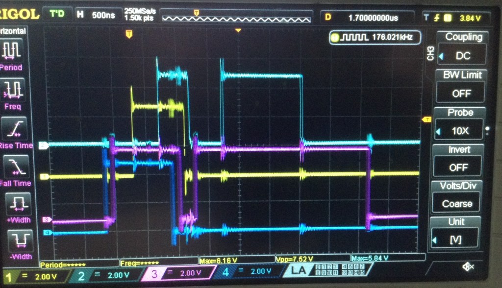
Ok, this is illuminating…
Dark blue is BC1 and purple is BDIR. As we can see here, it goes HIGH and then stays HIGH, well forever. I guess the first write is picked up as the INT0/INT1 interrupts I guess are queued up?
At this point I pulled the AVRAY out whilst it was running, and guess what? BDIR was still HIGH. So looking back over my test code, and I spot this:
#define BDIRLOW  {PORTC &= 0xF7;} // A2 LOW
#define BDIRHIGH {PORTC |= 0x04;} // A2 HIGH
Anyone? All together now…
Sigh. Yes, that 0xF7 should have been 0xFB. Or better yet, (~0x04).
So now I finally can see that the interrupts are, indeed, working as expected.
Try Again…
So at this point, I went back to the original 328 firmware, EPROM configuration and fuse settings, figuring that my test writes to pins isn’t going to help anything working.
And it still doesn’t work. Big sigh.
At this point I’m going to have to leave it again, because all I’ve really proved is that I can’t be trusted with both sides of a two-part system…
Kevin
