
Here are the build notes for my Korg Volca Modular MIDI to CV PCB.

Warning! I strongly recommend using old or second hand equipment for your experiments. I am not responsible for any damage to expensive instruments!
If you are new to microcontrollers, see the Getting Started pages.
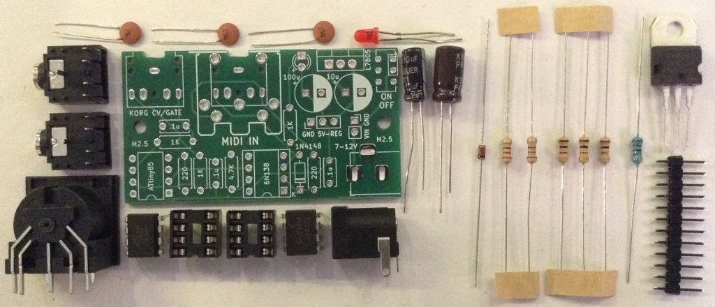
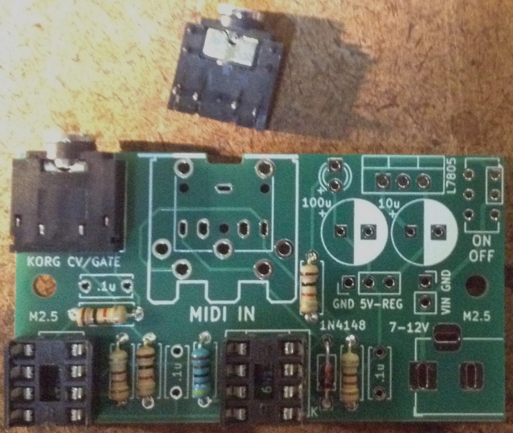
Bill of Materials
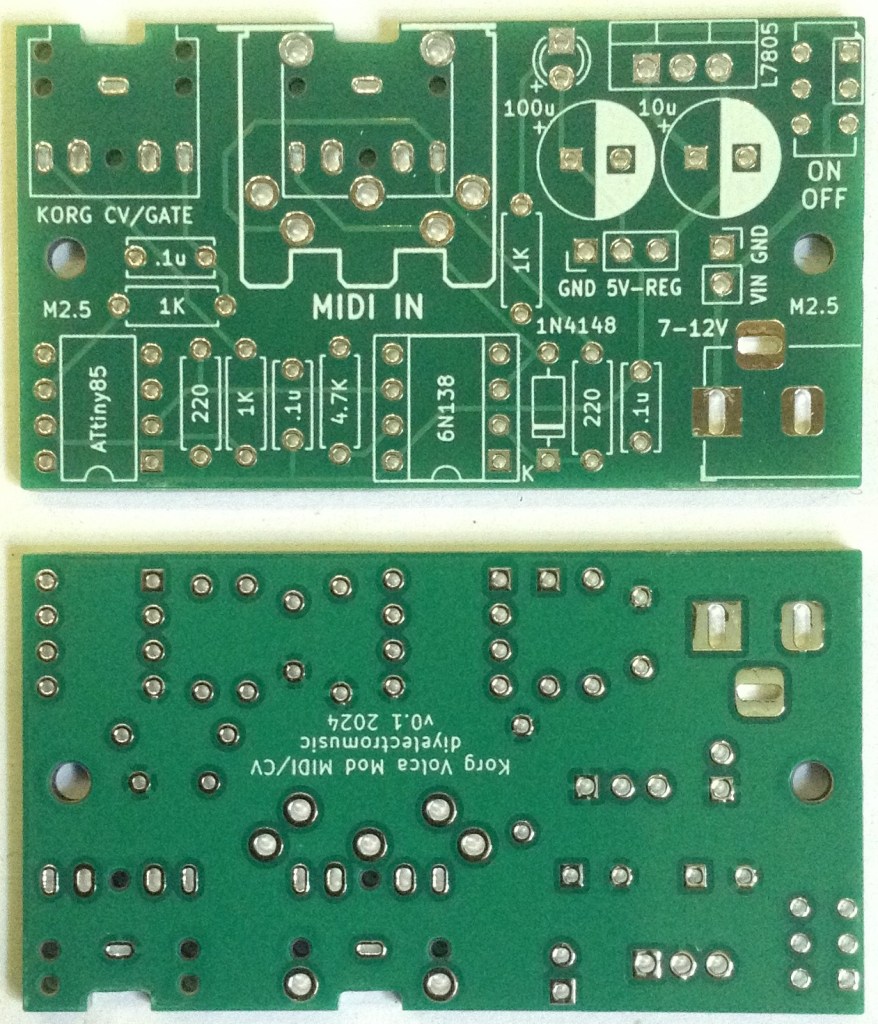
- Korg Volca Modular MIDI to CV PCB (GitHub link below).
- 1x ATtiny85 DIP-8.
- 1x 6N138 optoisolator DIP-8.
- 1x 1N914 or 1N4148 signal diode.
- 2x 220Ω resistors.
- 3x 1K resistors (one optional, for LED).
- 1x 4K7 resistor.
- 3x 100nF ceramic capacitors.
- 1x 3mm LED (optional).
- 1x 3.5mm stereo TRS pcb mount (see PCB and photos for footprint).
- Either 1x 3.5mm stereo TRS or 5-pin DIN socket (see PCB and photos for footprint).
- 2x 8-way DIP sockets (optional, recommended).
- Header pins (optional).
- 1x pin jumper (optional).
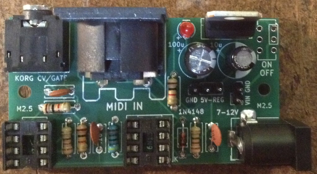
Power circuit (optional):
- 1x L7805 regular TO-220.
- 1x 10uF electrolytic capacitor.
- 1x 100uF electrolytic capacitor.
- 1x 2.1mm barrel jack socket (see PCB and photos for footprint).
- 1x on/off switch (optional).
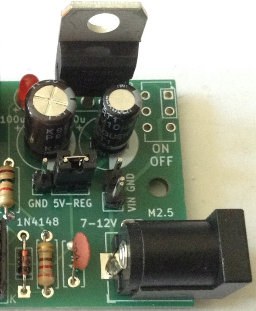
Power Options
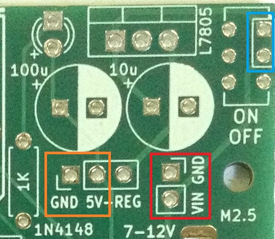
The PCB includes a regulator circuit to take a 7-12V input either via 2.1mm barrel jack or 2-pin jumper headers (red) to create the required 5V power supply.
The switch is optional. If not required, then the highlighted two pins (blue) can be connected with a wire bridge.
Alternatively, a regulated 5V supply can be provided directly via another jumper header (orange) in which case the barrel jack socket and all of the component footprints highlighted in the above photo can be omitted (other than the GND-5V header pins themselves).
When used with the built-in power supply, a link is required between “5V” (part of the orange highlight) and “REG”.
Note: when used with the barrel jack socket, I don’t see any reason why the VIN/GND (red) headers couldn’t be used for a “VOUT” connection too. If that had a couple of jumper wires to a second barrel jack, for example, it could potentially be used to power the Volca too.
See photos as part of the build for more details.
Build Steps
Taking a typical “low to high” soldering approach, this is the suggested order of assembly:
- All resistors and diode.
- DIP socket (if used) and TRS socket(s).
- Disc capacitors and LED.
- Jumper headers.
- Electrolytic capacitors.
- Other components.
Here are some build photos.
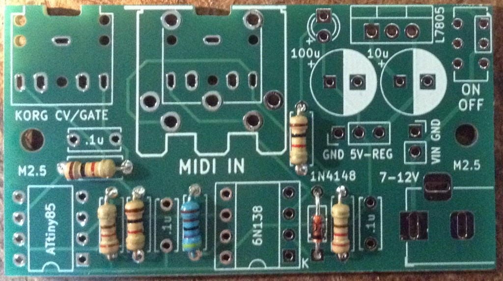
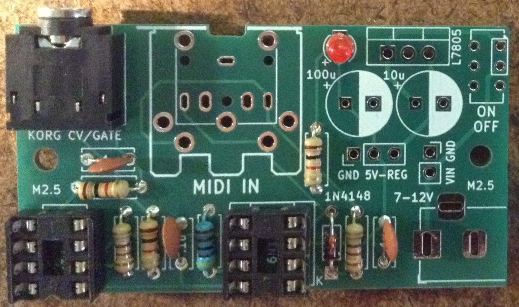
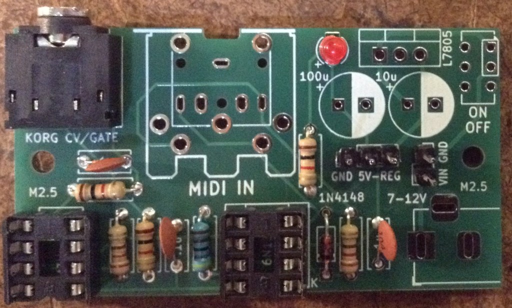
The order of installation for the larger components and connectors will depend on the exact configuration and components used. They can be installed last in whatever order makes sense.
Power Options
There are only three valid power configurations as follows.
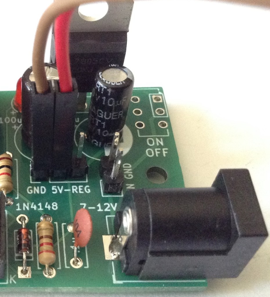
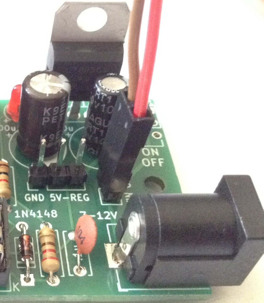
- Left: Installation of the jumper between 5V and REG to use the on-board regulator (other header connections are redundant).
- Centre: External connection to regulated 5V power supply (regulator and power circuitry is redundant).
- Right: External connection to non-regulated 7-12V supply (barrel jack socket is redundant).
WARNING: Never connect a jumper between GND and 5V across the “GND 5V-REG” headers.
With hindsight, mixing the options for adding external jumper wires (so requiring GND/5V) and linking 5V to REG (so requiring a jumper) was probably unwise, but it seemed like a neat optimisation at the time.
Initial Testing
I recommend performing the general tests described here: PCBs prior to installing the ATtiny85.
It is also worth verifying the operation of whatever power option has been implemented by checking for GND and 5V at the ATtin85 socket:
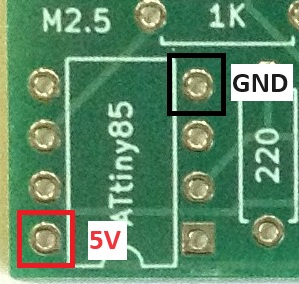
Then a programmed ATtiny85 can be installed and MIDI reception checked, checking the CV and gate signals with an oscilloscope.
The CV/Gate TRS out is compatible with the Korg Volca Modular, which means it has the following connections:
- TRS Left channel = Gate: 0V (off) or 5V (on).
- TRS Right channel = CV: 0V to 5V range.
Programming the ATtiny85
The code for the MIDI to CV converter can be found here: https://emalliab.wordpress.com/2019/03/02/attiny85-midi-to-cv/
To program the ATtiny85 requires the following:
- A USB programmer. I use the Sparkfun “Tiny AVR Programmer“.
- The ATtiny85 Arduino core by Spence Konde: https://github.com/SpenceKonde/ATTinyCore – I have v1.5.2 installed at the time of writing.
The key things to remember are:
- Set the programmer to “USBTinyISP” – if you get a choice, I used the “slow” version. Note: you won’t see a “port” with this one, it using the programmer directly.
- The clock setting requires is “Internal” 8MHz.
There are options in the code for the MIDI channel to listen to, the default being channel 1.
There is also a setting for the MIDI notes that correspond to generating 0V and 5V. The default lowest note is 36 – C2, and the default highest note is 96 – C7, giving 5 octaves across the 0-5V CV range.
In Use
Here are some of the average CV voltage readings I’m getting for various MIDI notes:
- C2: avge -80 mV; 0V max
- C3: avge 918mV; 1.2V max
- C4: avge 1.88V; 2.24V max
- C5: avge 2.88V; 3.28V max
- C6: avge 3.84V; 4.16V max
- C7: avge 4.81V; 4.96V max
Plotting those readings out on a graph (max in orange; average in blue) gives:

So, actually that probably isn’t too bad. The gate seems to work pretty well too.
Controlling the Korg Volca Modular
To hook it up to a Korg Volca Modular requires 3.5mm stereo jack to jack cable between the CV output and the Korg’s CV-IN socket. The two signals (CV/Gate) are then available o the corresponding patch points.
Patch the CV signal to the oscillator (green wire below) and the Gate to the first (AHR) function (blue wire) as follows:

In use, to my ears, the tuning doesn’t sound too bad to me across the range C2 to C7. Not sure about that very bottom C2… but then I wasn’t convinced that 0V really was 0V anyway.
PCB Errata
There are no issues currently known with this PCB however please note:
Check and double check the outputs before you let them anywhere near your Korg Volca! This is “use at your own risk”. I am not responsible for any dead Volcas….
Enhancements:
- As already mentioned, with hindsight, I probably should have separated out the external, 5V regulated pin headers from the 5V-REG jumper.
- I wanted a power LED but MIDI activity might have been more useful.
- I need to get a better power switch footprint! That was a bit of an afterthought and isn’t particularly useful as it stands.
- Another thing that might be useful would be a second barrel jack socket to allow power to be taken from the same source into the Volca.
Closing Thoughts
For a first practical application of both CV/Gate and the ATtiny85, I’m pretty pleased with how this works. It is certainly very responsive for the Korg. It is monophonic of course, as it only generates a single CV output but again that is fine for the Korg.
I know there are mods for a Volca Modular to give it MIDI directly – there are patch points readily available on the PCB inside, as I mentioned before – I just didn’t want to be opening mine up so soon and seeing as CV/Gate is readily available, I don’t really see the need.
I might see if I can knock-up a 3D printed case for this to make a nice, self-contained unit.
Kevin

Good afternoon! Thank you very much for your project, this is what I have been looking for for a long time! But I’m having problems with the Attiny85 firmware. I do not have a Sparkfun programmer, and I cannot purchase it, since I am from Russia and there is no delivery here. Tell me, is there any other way I can program Attiny to make it work? Thanks a lot in advance!
LikeLike
I’ve not done it myself, but I’m pretty sure if you have an Arduino then there is an Arduino sketch that enables it to be used as an AVR programmer, and I think that can be used to program an ATtiny. Look up ArduinoISP.
I’m sure there are other ways too, but I just went for the simplest available to me at the time. I don’t have a lot of experience with the ATtiny I’m afraid, but there is quite a lot of information out there about it.
Good luck!
Kevin
LikeLike
Did you know of the Korg Modular EURO project? There was a facebook page, they made into a small production with patreon I think, it was a full Volca Modular to Eurorack conversion kit, with extruded pins in the internal side, normalled to minijacks.
It’s become impossible to find about the makers or the project itself anymore.
Even this page, was rather difficult to find. Props.
LikeLiked by 1 person
I’m not sure I do. I seem to recall there were some who took the insides of a volca and stuck it into a eurorack style case, but I can’t find the details at the moment 🙂
LikeLike