Here are the build notes for my Raspberry Pi Zero MIDI PCB.
Warning! I strongly recommend using old or second hand equipment for your experiments. I am not responsible for any damage to expensive instruments!
If you are new to microcontrollers and single board computers, see the Getting Started pages.
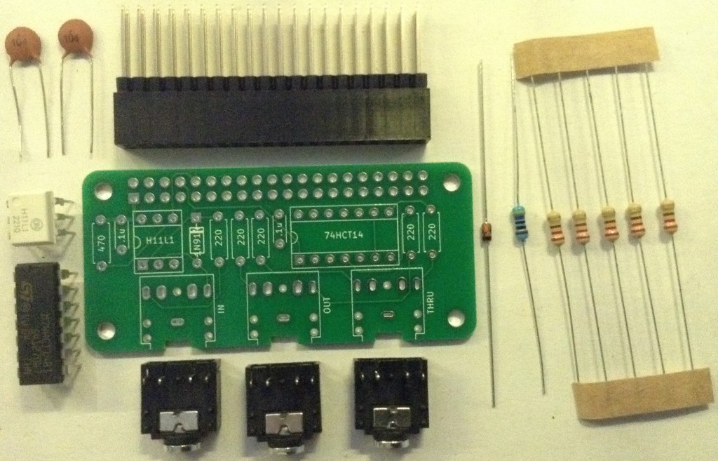
Bill of Materials
- Raspberry Pi Zero MIDI PCB (GitHub link below).
- 1x H11L1.
- 1x 74HCT14 (NB: Must be the HCT version, not the HC).
- 1x 1N914 or 1N4148 signal diode.
- 5x 220Ω resistors.
- 1x 470Ω resistor.
- 2x 100nF ceramic capacitors.
- 3x stereo TRS PCB-mount sockets (see photos for footprint).
- Optional: 6-way DIP socket; 14-way DIP socket.
- 1x 2×20-way GPIO normal or extended header.
Build Steps
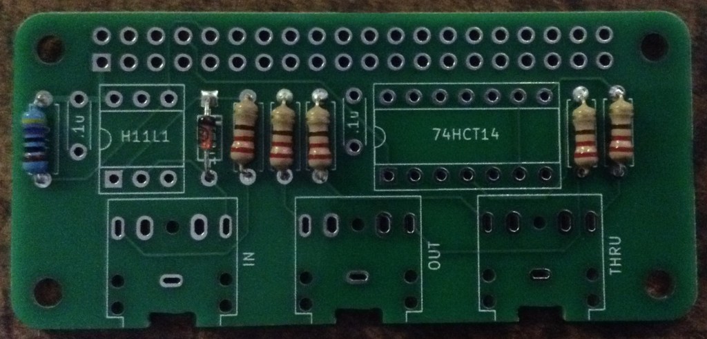
Taking a typical “low to high” soldering approach, this is the suggested order of assembly:
- All resistors and diode.
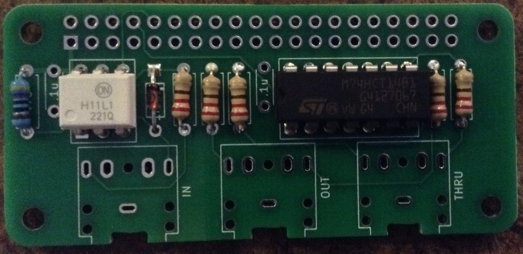
- DIP sockets (if used) or H11L1 and 74HCT14.
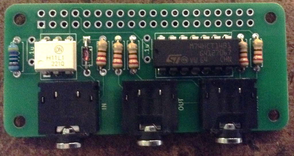
- TRS sockets.
- Disc capacitors.
- GPIO header.
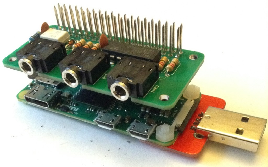
The type of GPIO header used will depend on the final intended use. I used an extended header as I want to be able to use this board between a Zero and my RPi Zero MiniDexed IO Board. Having said that, it is just a little too tall. Ideally it would be slightly shorter in the plastic body of the header and then with slightly shorter pin length.
Other options for mounting could be to have an extended header on the Zero itself and then this could sit beneath it with additional IO boards on top.
The components aren’t so tall, especially if not using DIP sockets, that it can’t be directly soldered onto a Zero too.
As mentioned in the design, this board only uses RX/TX/GND and power so a full GPIO header isn’t actually required.
In principle it could also be used with a 26-way header on an original Pi V1 although the mounting holes wouldn’t line up.
I’ve opted for flexibility so am using a set of extended GPIO headers.
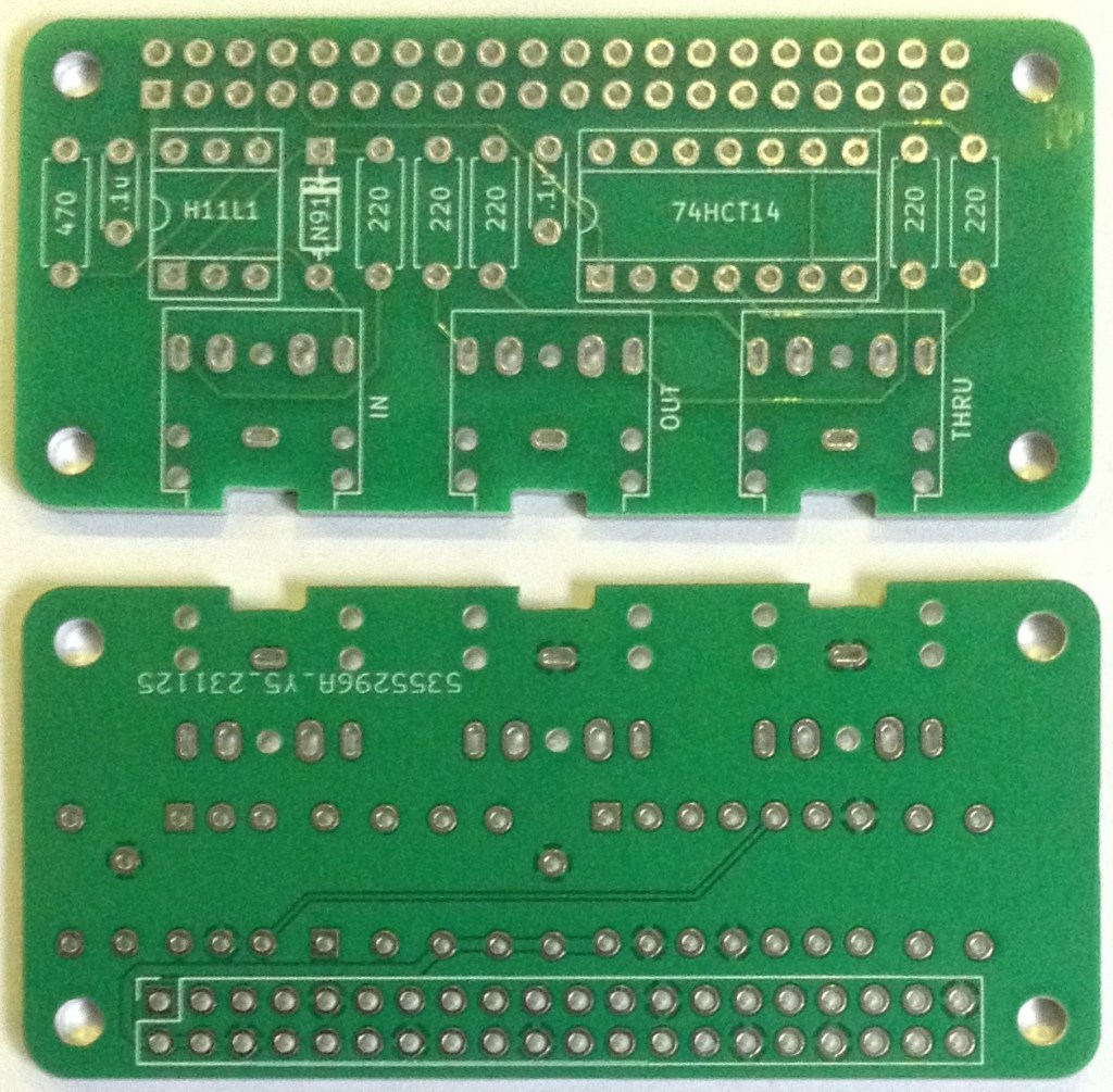
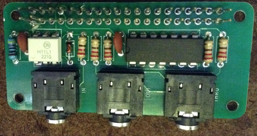
Here are some build photos.
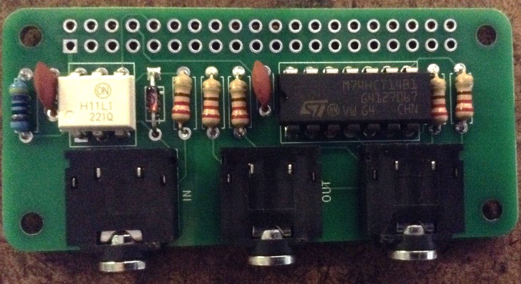
Note: when it comes to the GPIO header it isn’t necessary to solder all 40 connections. The following is the minimum recommended set to solder (highlighted in red) – note the last two are not functionally used, but I’ve soldered them for structural rigidity!
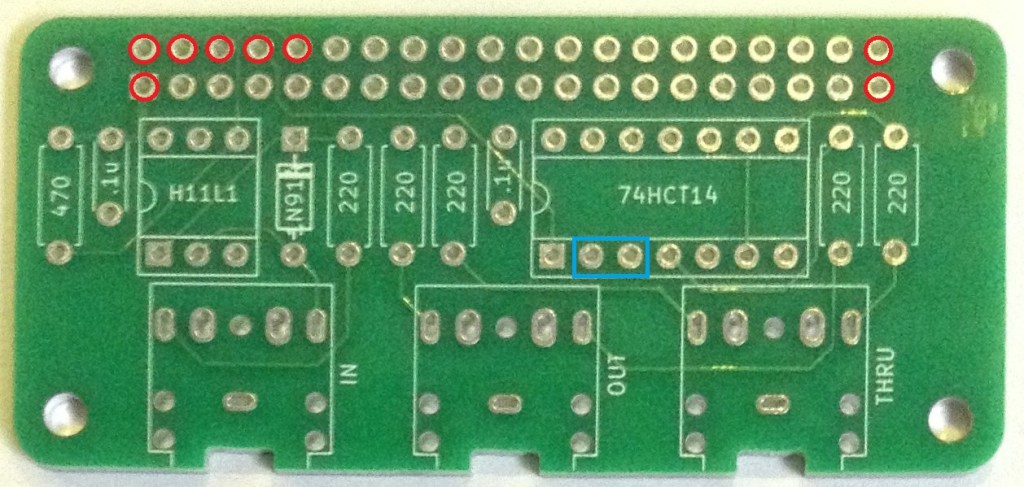
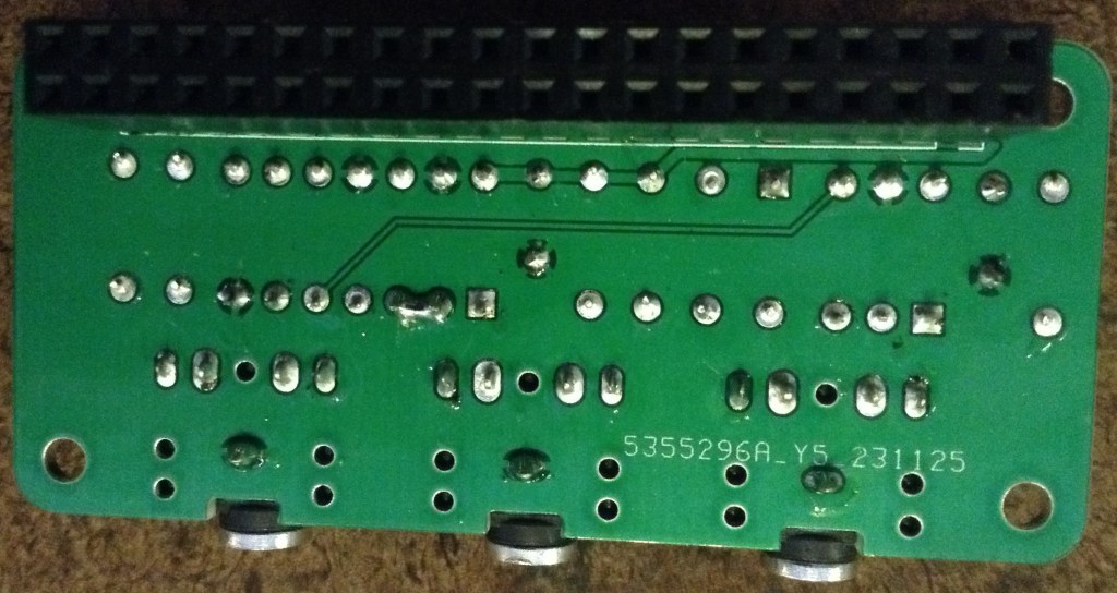
As a final step, the two pin connections highlight above in blue need to be linked with a bit of joining wire or solder. This is the missing connection mentioned in the errata. This is most easily done once the rest of the board is complete with a wire or solder bridge on the underside of the board. This can be seen in the photo below.
Testing
I recommend performing the general tests described here: PCBs.
If using MiniDexed then the hardware MIDI through can be checked by connecting the MIDI IN and THRU ports to a PC MIDI interface. Any MIDI information sent to the Pi should be echoed straight back to the MIDI THRU port.
If using MiniDexed then the hardware MIDI OUT can be checked by using the following (software) MIDI THRU configuration in minidexed.ini:
MIDIThru=ttyS1,ttyS1If using MiniDexed in USB Gadget mode, then the device can actually act as a USB to MIDI serial OUT interface if the following (software) MIDI THRU configuration is used:
MIDIThru=umidi1,ttyS1PCB Errata
There are the following issues with this PCB:
- As mentioned there is a missing link between pins 2 and 3 of the 74HCT14.
Enhancements:
- The PCB could support the use of DIN MIDI sockets as well as TRS if it was made bigger.
Closing Thoughts
Weirdly I noticed the missing link prior to testing which is probably a good thing as the MIDI OUT socket did seem to work most of the time without it!? I still don’t quite know why but wonder if there was some odd signal cross-over happening in the 74HCT14. Or maybe there was a weird connection via the GND links or something. It wasn’t fully reliable – it sometimes worked and sometimes didn’t. Without the link, the signal on the Pi’s TX pin was quite skewed too so maybe some odd capacitance thing was going on somewhere. All very odd.
Once the link was made it all seemed to work fine, and the TX signal had nice square edges again, so whilst annoying it was a relatively simple fix.
Kevin
