This is the build guide for the Analog IO Board PCB.

Warning! I strongly recommend using old or second hand equipment for your experiments. I am not responsible for any damage to expensive instruments!
These are the key Arduino tutorials for the main concepts used in this project:
- Simple Potentiometer Breakout
- Arduino Multi-pot Mozzi FM Synthesis
- Arduino MIDI Mux Step Sequencer
- Arduino Mozzi FM Synthesis with MCP3008
If you are new to Arduino, see the Getting Started pages.
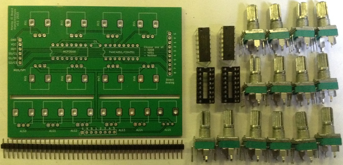
Bill of Materials
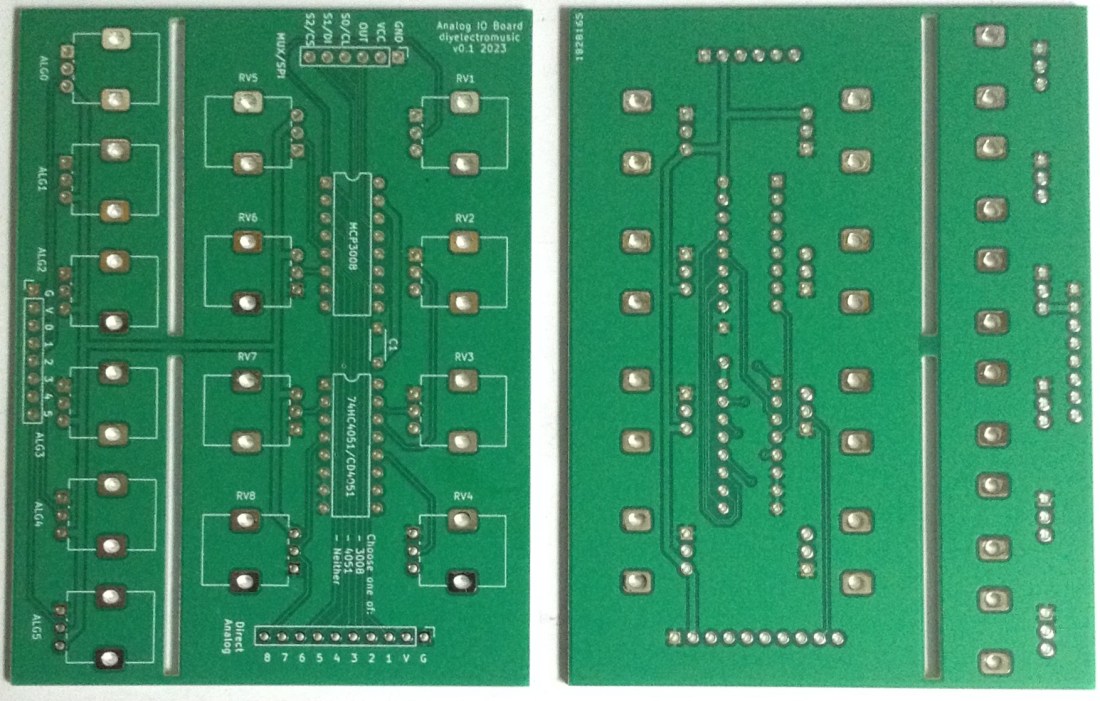
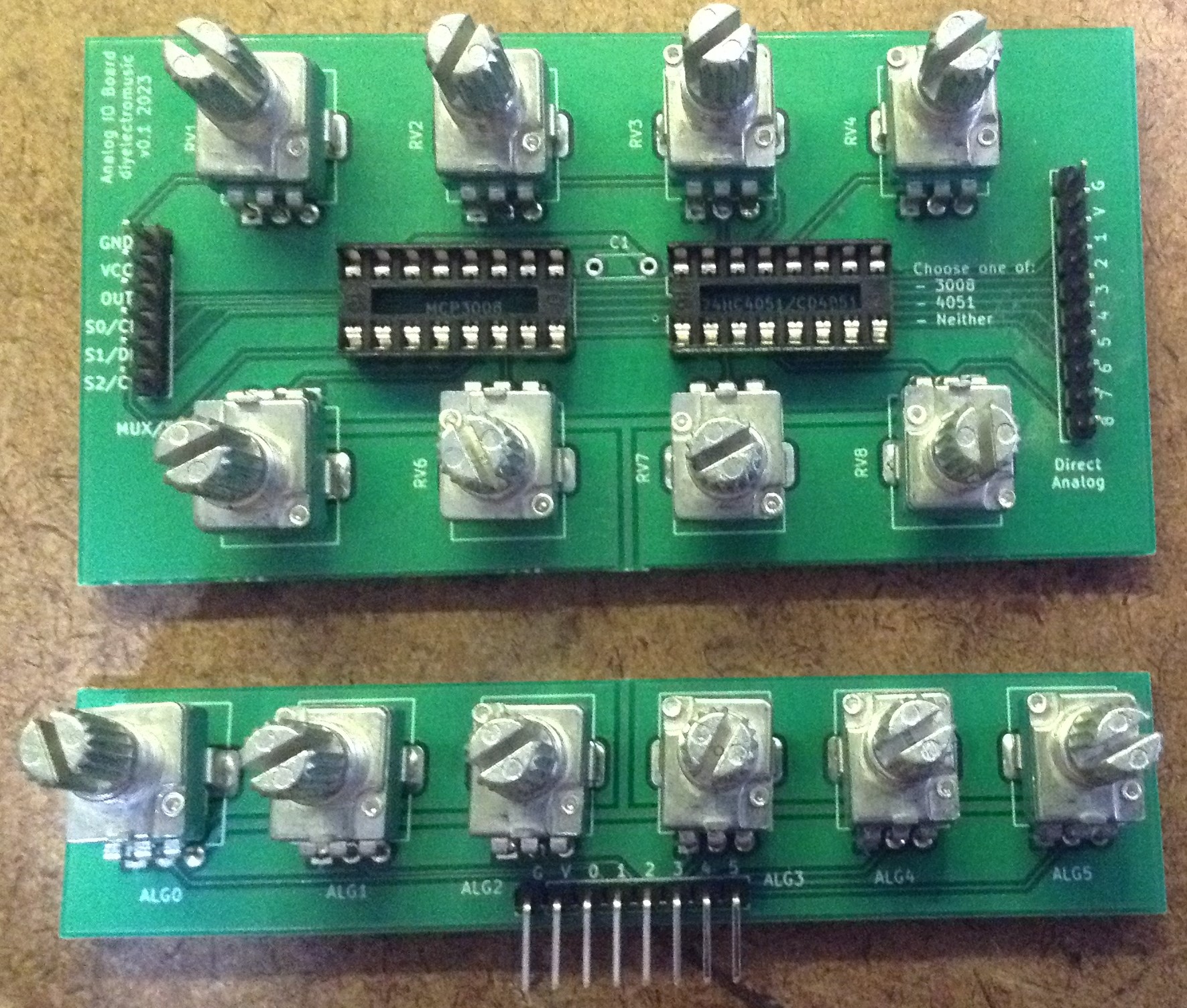
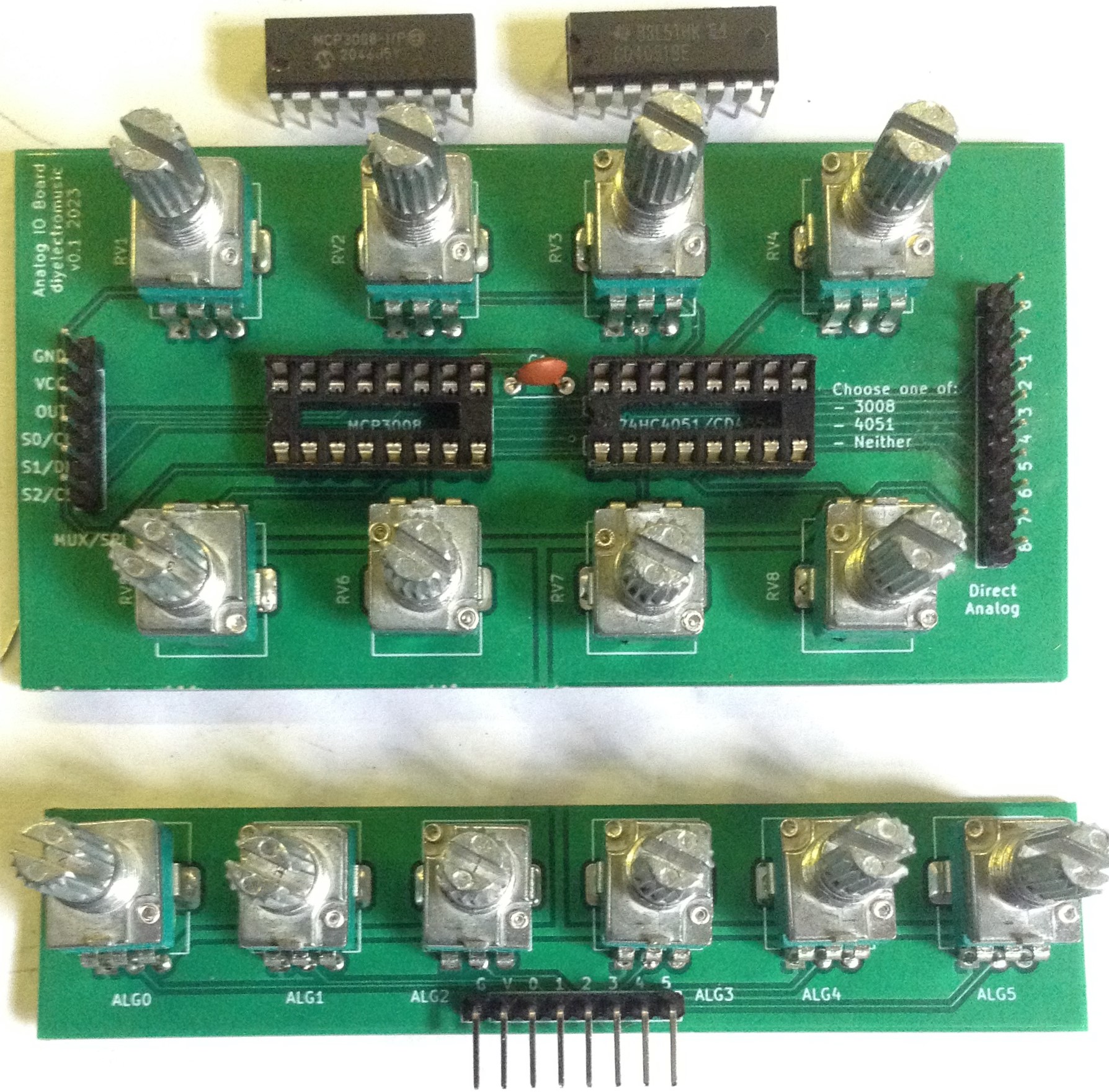
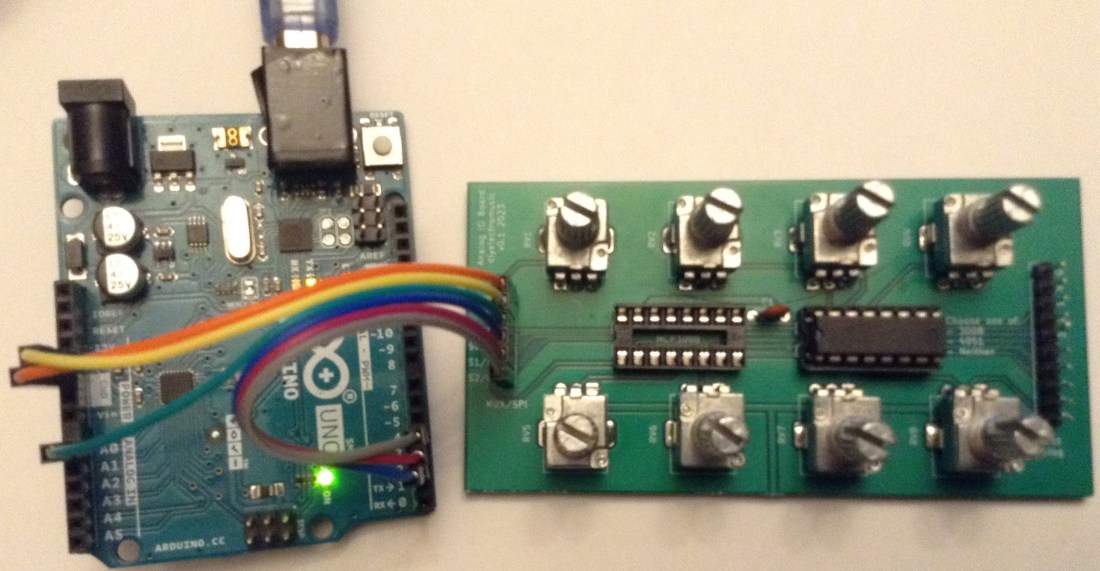
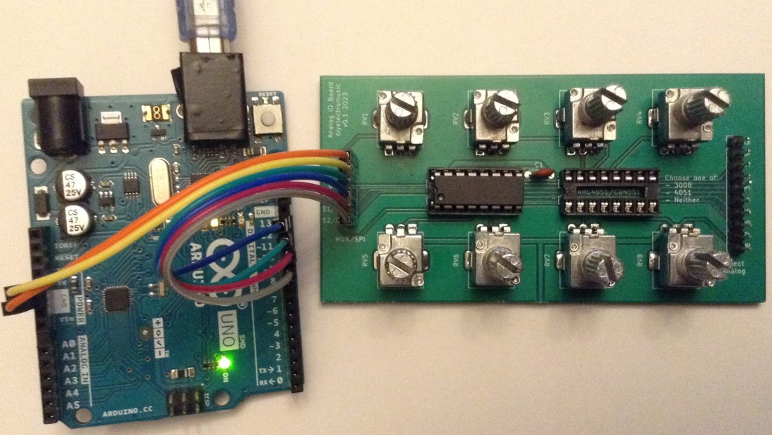
PCB Photo
- Analog IO Board PCB (GitHub link below).
- 6, 8 or 14 10kΩ PCB mount potentiometers (see photos and PCB for footprint).
- Optional: MCP3008.
- Optional: 74HC4051 or CD4051.
- Optional: 1 or 2 16-way DIP socket.
- Optional: 1x 100nF capacitor (if either chip is used).
- Pin headers – either straight or right-angled or a mixture.
Build Steps
This is the recommended order of build:
- If required split the PCB and file off any rough edges.
- DIP sockets (if used).
- Capacitor (if used).
- Pin headers.
- Potentiometers.
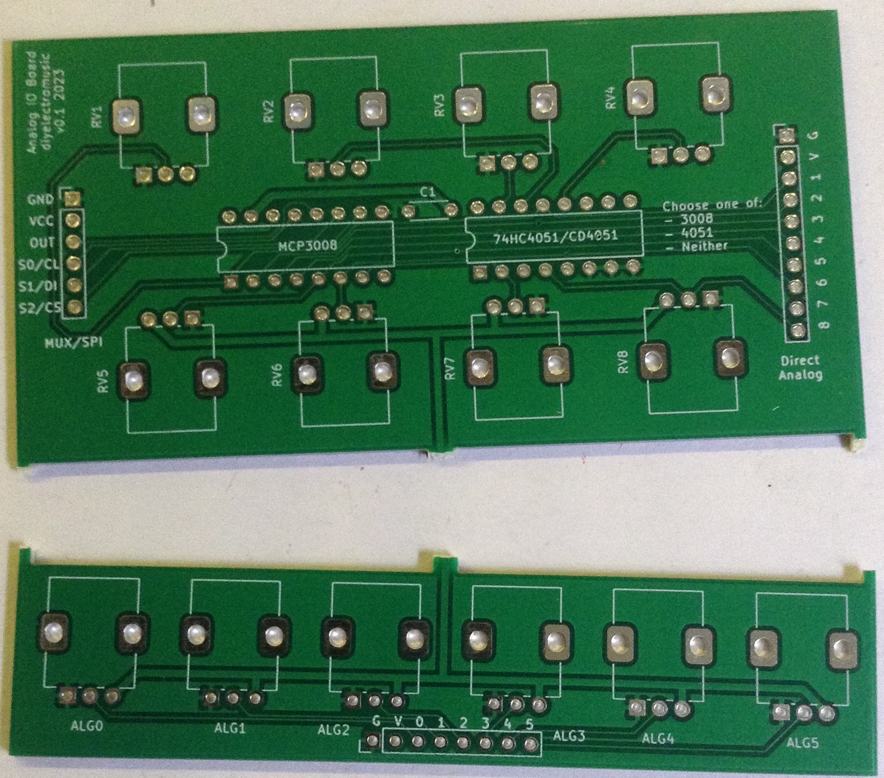
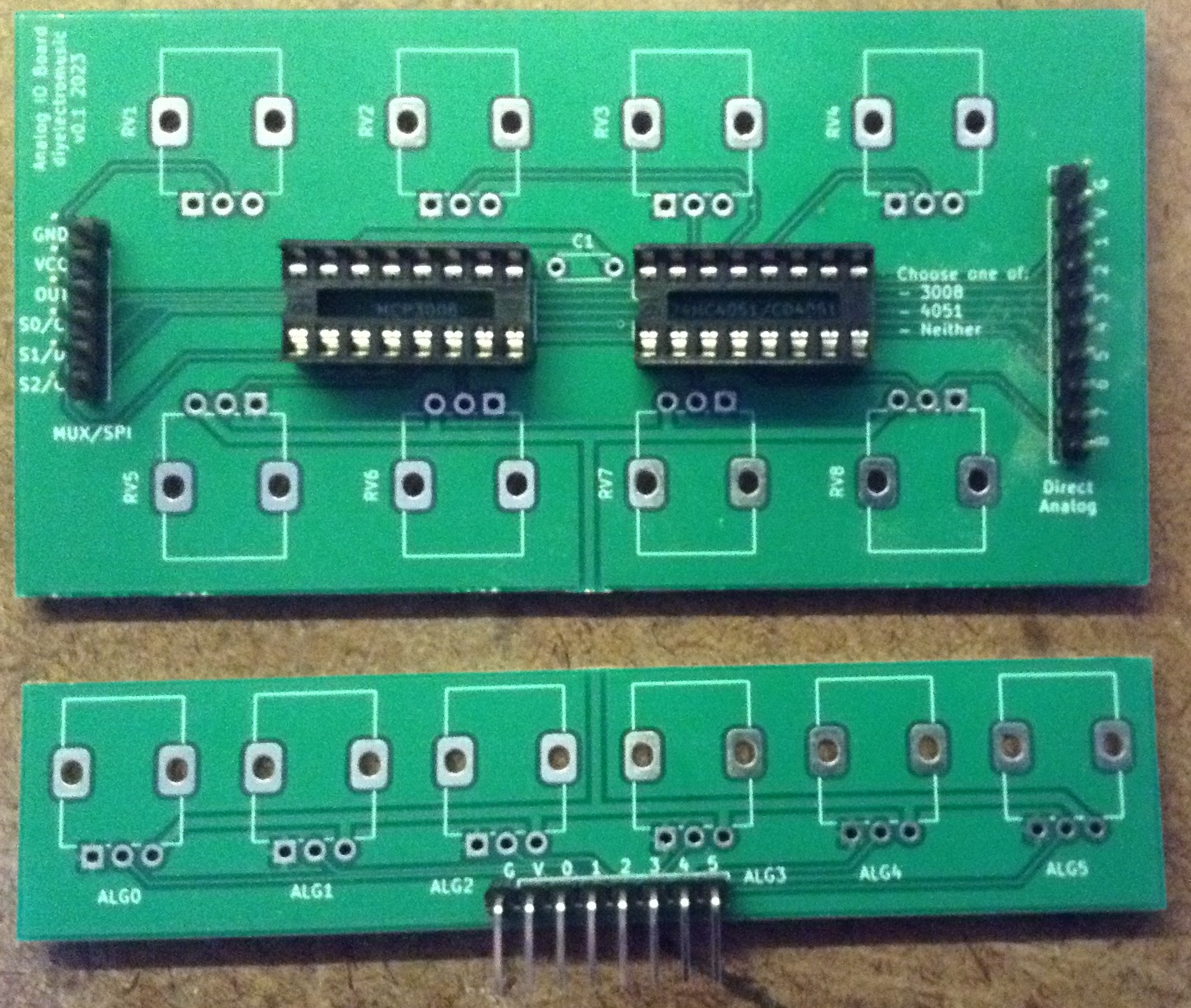
Here are some build photos. Note that this shows both DIP sockets populated, but in practice only one or neither may be used. It also shows all pin headers populated and again for the 8-way board it is more likely that only one of the left (if used with the MCP3008 or 4051) or the right (if used directly) is used.
Testing
I recommend performing the general tests described here: PCBs. Note that the resistance between VCC and GND at any of the pin headers will relate to parallel resistance of the potentiometers used. So if 10kΩ pots are used, then the 8-way board would read ~1K2Ω and the 6-way board would read ~1K6Ω.
When testing, be sure to connect V and G the right way round. For some reason I kept wanting to connect them wrongly!
Board Options
All these examples show how the analog IO board can be used with an Arduino Uno or Nano but the same principles can be applied to any other microcontroller, such as the Raspberry Pi Pico.
The example code is all “Arduino C” but again equivalents can be used in Micropython or Circuitpython as required.
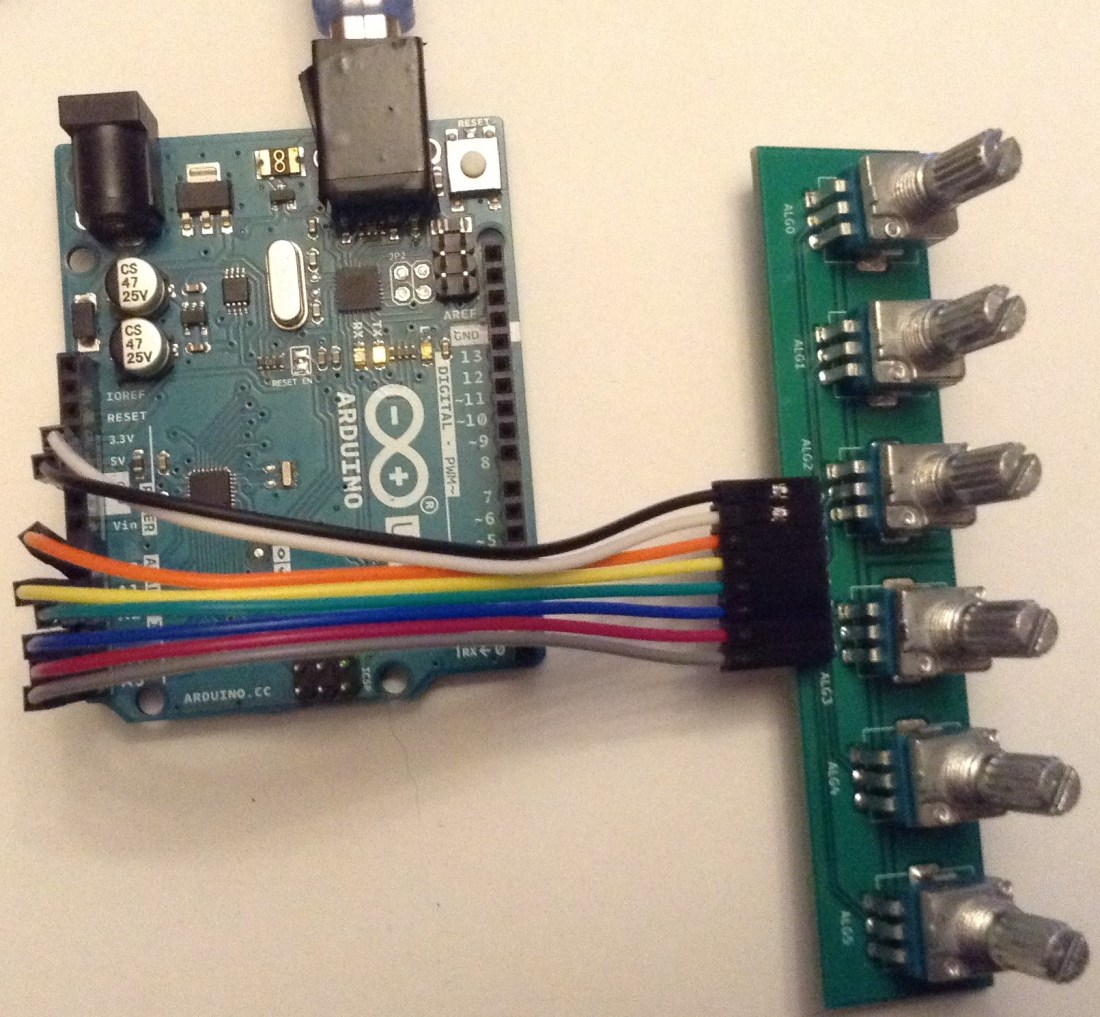
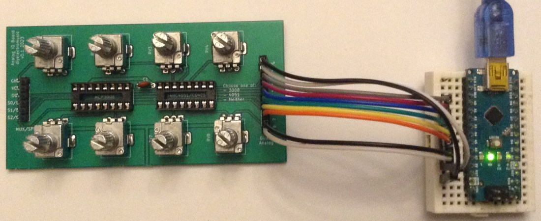
Direct connection
To use with an Arduino Uno or Nano (a Nano is required to test all 8 pots) with a direct connection, the 0-5 (bottom header) or 1-8 pins (right hand header) should be connected to A0 to A5 or A0 to A7 as required. It also needs a connection to 5V and GND.
The following code can be used to check the pots are working correctly.
void setup() {
  Serial.begin(9600);
}

void loop() {
  for (int i=0; i<8; i++) {
    int aval = analogRead(A0+i);
    Serial.print(aval);
    Serial.print("\t");
  }
  Serial.print("\n");
  delay(100);
}
4051 Multiplexer
The multiplexer can be used in the right-hand DIP socket. A 74HC4051 or CD4051 should be fine. This will use the left-hand header connected as follows:
- GND, VCC to GND and 5V.
- OUT to one of the analog inputs (e.g. A0).
- S0, S1, S2 to three digital pins (e.g. D2-4).
void setup() {
  Serial.begin(9600);
  pinMode (2, OUTPUT);
  pinMode (3, OUTPUT);
  pinMode (4, OUTPUT);
}

void loop() {
  for (int i=0; i<8; i++) {
    if (i & 1) { digitalWrite(2, HIGH);
        } else { digitalWrite(2, LOW);
        }
    if (i & 2) { digitalWrite(3, HIGH);
        } else { digitalWrite(3, LOW);
        }
    if (i & 4) { digitalWrite(4, HIGH);
        } else { digitalWrite(4, LOW);
        }
    int aval = analogRead(A0);
    Serial.print(aval);
    Serial.print("\t");
  }
  Serial.print("\n");
  delay(100);
}
MCP3008 SPI IO Expander
The MCP3008 can be used in the left-hand DIP socket. This will use the left-hand header connected as follows:
- GND, VCC to GND and 5V.
- Arduino 12 (MISO) – OUT (DOUT)
- Arduino 13 (CLK) – CL (CLK)
- Arduino 11 (MOSI) – DI (DIN)
- Arduino 10 (SS) – CS (CS/SHDN)
To use the MCP3008 requires a library. I’ve used Christopher Baker’s MCP3XXX library which can be found here: https://github.com/bakercp/MCP3XXX.
#include <MCP3XXX.h>
MCP3008 adc;

void setup() {
  Serial.begin(9600);
  adc.begin();
}

void loop() {
  for (int i=0; i<8; i++) {
    int aval = adc.analogRead(i);
    Serial.print(aval);
    Serial.print("\t");
  }
  Serial.print("\n");
  delay(100);
}
PCB Errata
There are the following issues with this PCB:
- None known at this time.
Enhancements:
- I might consider swapping V and G on the headers.
Sample Applications
There are many applications on this blog for these breakouts. On my blog, I’ve used potentiometers to control synth parameters, sequencers, MIDI controllers, drum machines, and more. The basics of using directly connected pots, MCP3008 and a multiplexer are covered in the following:
- Arduino Multi-pot Mozzi FM Synthesis
- Arduino MIDI Mux Step Sequencer
- Arduino Mozzi FM Synthesis with MCP3008
A good starting place for further experiments might be to browse through the “potentiometer” tag here: https://diyelectromusic.wordpress.com/tag/potentiometer/
Closing Thoughts
I’m really pleased with how these boards work and the options they now allow. I can see them being really useful going forward.
These boards have been manufactured using the Seeed Fusion PCB service, which I am happy to continue to recommend. They have been supported with discount vouchers that I’ve been sent by Seeed for my previous projects.
Kevin
