This is the build guide for my Arduino Nano Mozzi Experimenter Shield PCB.
Warning! I strongly recommend using old or second hand equipment for your experiments. I am not responsible for any damage to expensive instruments!
These are the key Arduino tutorials for the main concepts used in this project:
If you are new to Arduino, see the Getting Started pages.
Bill of Materials

- 1x Arduino Nano
- Arduino Nano Mozzi Experimenter Shield PCB (GitHub link below)
- 1x 330Ω resistor (was 75Ω)*
- 4x 220Ω resistors
- 1x 1.5K resistor (was 270Ω)*
- 1x 4K7 resistor
- 6x 10K linear (B) potentiometers (PCB mount, see photos for footprint)
- 1x 68nF ceramic capacitor
- 2x 100nF ceramic capacitors
- 1x 10uF electrolytic or non-polar capacitor
- 1x 100uF electrolytic capacitor
- 1x 1N914 or 1N4148 signal diode
- 1x 6N138 optoisolator
- Optional: 8-pin DIP socket
- 2x 180 degree DIN PCB mounted sockets
- 3x 3-way pin headers and jumper
- Optional: PCB mounted DPDT switch could replace two sets of jumpers (see photos for footprint)
- 1x 3.5mm stereo TRS audio jack socket, PCB mounted (see photos for footprint)
- Optional: 1x 2.1mm barrel jack socket (see photos for footprint)
- Optional: 2x 15-way header sockets
* See the discussion about values here: Arduino PWM Output Filter Circuit.
The circuit can be powered using the Arduino Nano’s mini-USB socket or via 7-12V via the 2.1mm barrel jack. If only using the Arduino’s USB power then the barrel jack socket, 100uF and top-most 100nF capacitors can be omitted.
The 8-way DIP socket for the optoisolator and 2x 15-way headers for the Arduino are optional, but recommended.
Note that the power jack is CENTRE NEGATIVE polarity.
There is a MIDI enable/disable function which can be either two sets of 3-way headers with jumpers or a PCB mounted DPDT switch with a footprint that matches that of the pin headers.
There is another 3-way pin header and jumper to select the audio output to be either D3 or D9.
The potentiometers are mapped to A0-A3, and A6, A7 as labelled on the board itself.
The audio output is a stereo jack socket, but the same mono signal is fed to both channels.

Build Steps
Taking a typical “low to high” soldering approach, this is the suggested order of assembly:
- All resistors and diode.
- DIP socket (if used), TRS socket, and DPDT switch (if used).
- Disc capacitors.
- 3-way jumper headers.
- Arduino header sockets.
- Barrel jack socket.
- Non-polar/electrolytic capacitors.
- DIN sockets.
- Potentiometers.
Important notes:
- As already stated the power jack is centre-negative.
- The Arduino should be oriented so that the mini USB socket is at the bottom.
- The TRS audio output should be a line-level, stereo output.
- There is minimal protection on the MIDI OUT circuitry.
- The pots read 0 when fully clockwise and 1023 when fully anticlockwise (which is backwards to how I would like them!).
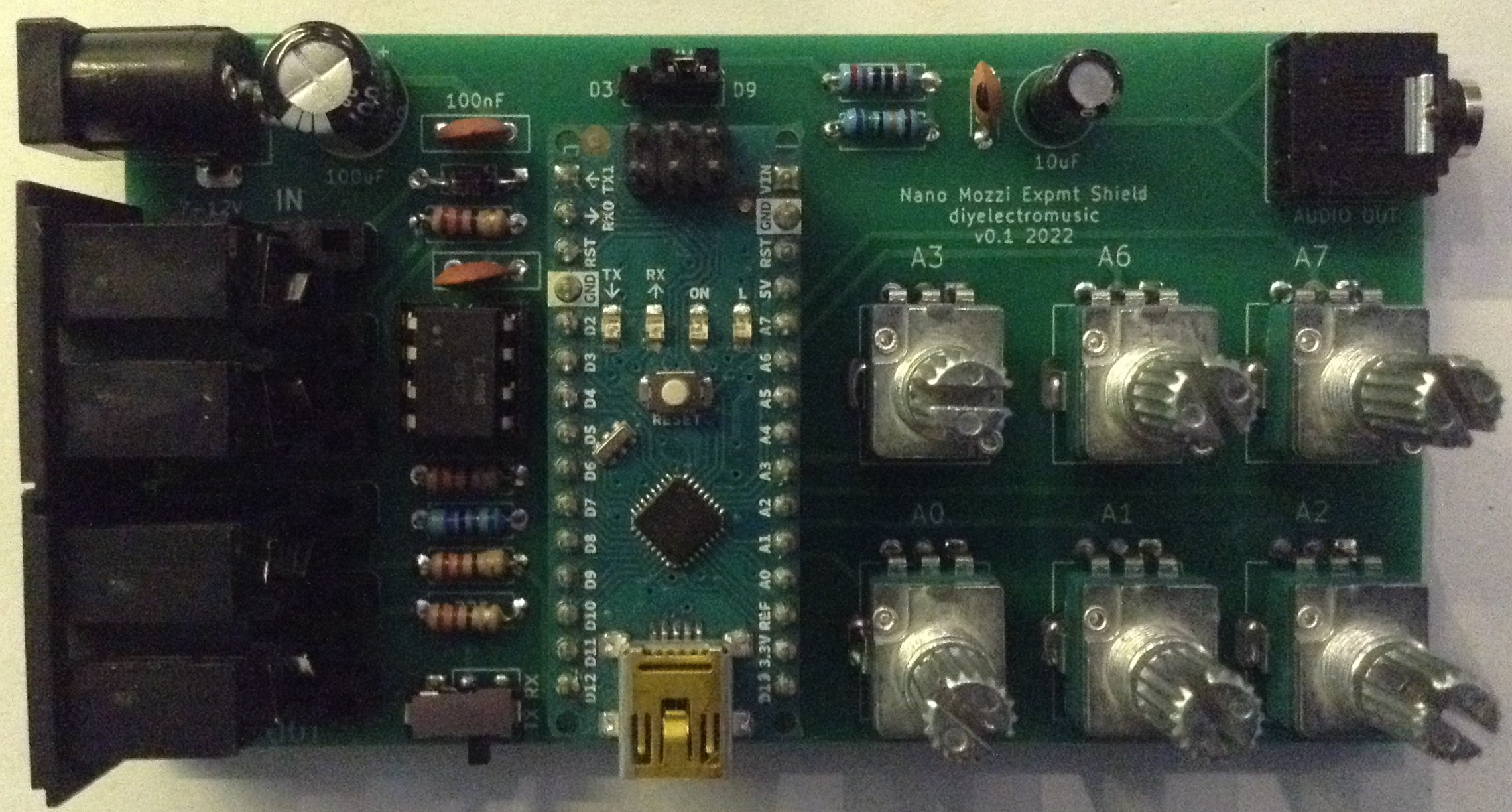
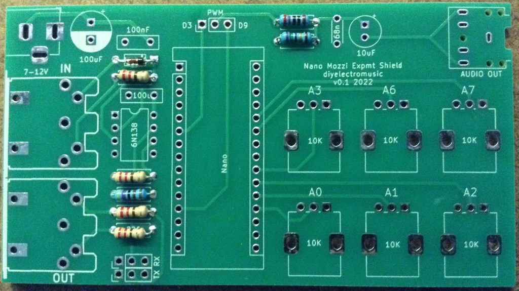
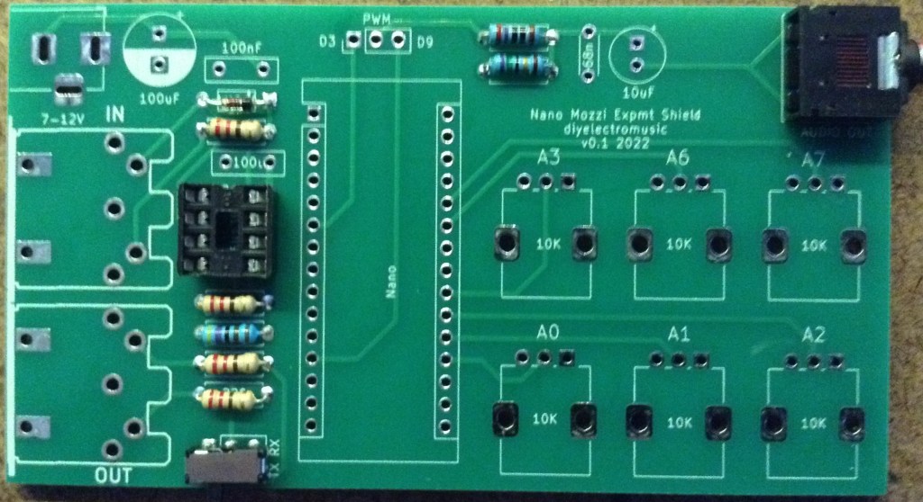
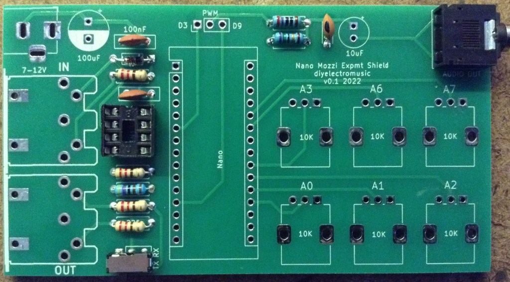
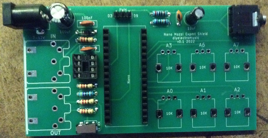
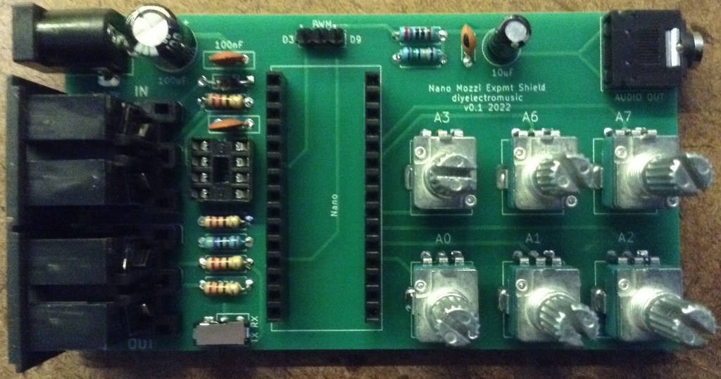
Here are some build photos.
Testing
I recommend performing the general tests described here: PCBs.
Note that as there are six 10K potentiometers linking 5V and GND, expect to see a resistance of 10K/6 or approx 1K7 between them.
If using the barrel jack, then that will go to VIN on the Arduino, so don’t expect to see a 5V reading until the Nano is in place. Without the Nano there should be no connection between the barrel jack (VIN) and the 5V traces.
PCB Errata
There are the following issues with this PCB:
- The barrel jack is CENTRE NEGATIVE (sorry).
- The pots are “backwards” in that zero is fully clockwise and full is anti-clockwise.
- The switch/headers should have a label to show which position is enabled and which is disabled.
- There should be some indication of which way up to plug in the Nano (USB down in case you were wondering).
And whilst not an errata as such, the PWM filter works much better replacing the 270Ω and 75Ω resistors with 1.5K and 330Ω respectively.
Enhancements:
- It might be useful to break out A4 and A5 for two extra pots.
- Alternatively it might be useful to have headers for an I2C connection.
- The MIDI OUT is a simple, unbuffered circuit.
- It might be useful to include TRS socket footprints for MIDI as an option too.
Sample Applications
Here are some applications to get started with:
- Arduino Multi-pot Mozzi FM Synthesis – Revisited
- Arduino Mozzi String Synth
- Arduino PWM Sound Output
I’ve taken the opportunity to update the FM synth sketch to include an option to reverse the pots in software. I did just try to use it “as is” but I just couldn’t get my head around turning them “the wrong way”. This is the configuration to use for this PCB.
#define POT_REVERSE 1
#define WAVT_PIN 0 // Wavetable
#define INTS_PIN 1 // FM intensity
#define RATE_PIN 2 // Modulation Rate
#define MODR_PIN 3 // Modulation Ratio
//#define AD_A_PIN 6 // ADSR Attack
//#define AD_D_PIN 7 // ADSR Delay
#define FREQ_PIN 7 // Optional Frequency Control
This is only using five of the six pots (A6 is unused). To control the ADSR rather than frequency, uncomment the appropriate lines above and comment out FREQ_PIN.
Closing Thoughts
I’m still a little annoyed about the pots! But apart from that (and it’s nothing a little software update can’t cope with) this seems to work really well. My next step is to try this with an Arduino Nano Every as I’m working on an update of Mozzi for the Every and would like to get rid of the jumper wires to my board!
These boards have been manufactured using the Seeed Fusion PCB service, which I am happy to continue to recommend. They have been supported with discount vouchers that I’ve been sent by Seeed for my previous projects.
Kevin
