I’ve been using my solderless breadboard version of my Arduino PWM Output Filter Circuit quite a lot so thought it might be useful to commit it to protoboard and build it onto a simple shield.

Warning! I strongly recommend using old or second hand equipment for your experiments. I am not responsible for any damage to expensive instruments!
If you are new to Arduino, see the Getting Started pages.
Parts list
- 1x 1.5K resistor (was 270Ω)*
- 1x 330Ω resistor (was 75Ω)*
- 1x 68nF capacitor
- 1x 10uF non-polar capacitor
- 3.5mm stereo jack socket
- Male headers
- Arduino stacking headers
- Proto shield and jumper wires
* See discussion about values here: Arduino PWM Output Filter Circuit.
The Circuit

I particularly wanted to have the option of using Pin 9 (on Timer 1) or Pin 3 (on Timer 2) for the PWM output so I’ve included a jumper that allows you to select which pin to connect to the output circuit.
I’ve also included test points for pre and post filter (bottom left) and a switchable MIDI module connection hooked up to RX/TX.
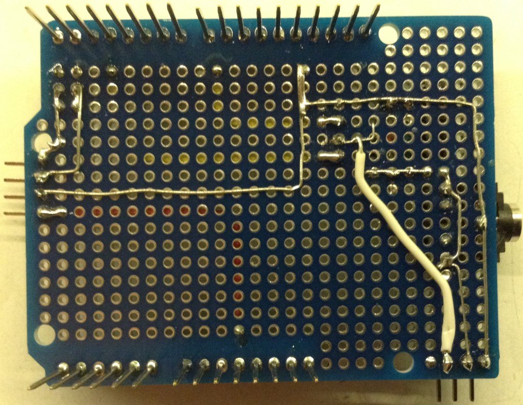
Here are a couple of photos of the build.
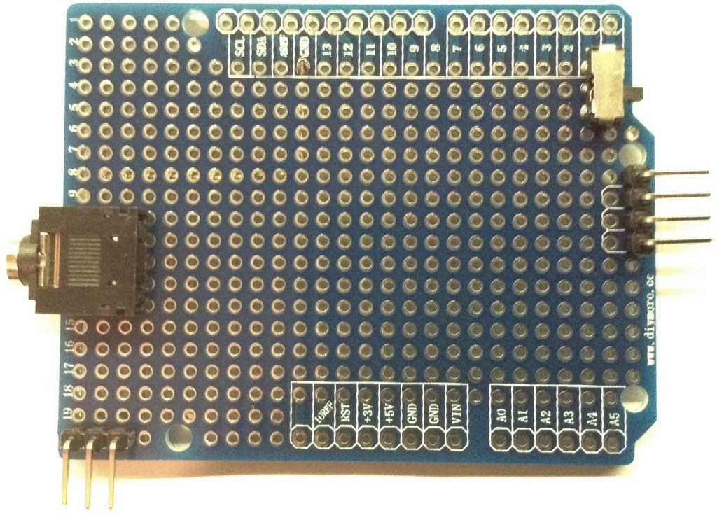
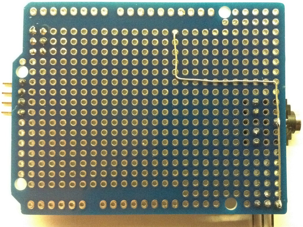
Starting with the headers, switch, socket and part of the GND wire underneath, then basically just going round adding the extra components and joining it up. The stacking headers are added last.
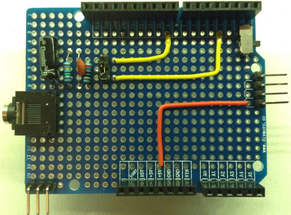
I’ve used stacking Arduino headers and right angle male headers to make this easy to use within a stack of other headers or simply to add jumper wires to the rest of the unused IO pins.
I was tempted to go the whole way and put a full MIDI transmit circuit and 3.5mm MIDI jack, but opted to keep it simple and just leave the option for easy hooking up to one of the Ready-Made MIDI Modules.
This should be really useful for further experiments.
Kevin
