Here are the build notes for my Atari 2600 Controller Shield PCB Design.
Recall from my design notes that this version doesn’t deal with paddles very well
Here is an updated version that supports paddles better, but at the expense of requiring more complex code to read them: Atari 2600 Controller Shield PCB Revisited.

Warning! I strongly recommend using old or second hand equipment for your experiments. I am not responsible for any damage to expensive instruments!
If you are new to Arduino, see the Getting Started pages.
Bill of Materials
- PCB (GitHub link below)
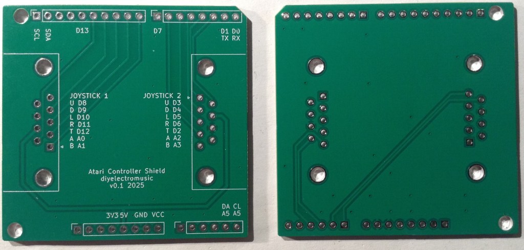
- 2x 9-pin D-type connectors – PCB mounted (see photos and PCB for footprint).
- Optional: Arduino headers: 1×6-way, 2×8-way, 1×10-way
- Or: pin headers

The above photo shows the 9-pin D-type connectors from various angles. The spacings are as follows:
- Pin spacing: 2.77mm
- Spacing between pin rows: 2.84mm
- Distance from pins to edge of connector: 7.7mm
- Mounting hole distance to edge of connector: 9.12mm
- Mounting hole distance: 25.0mm

Build Steps
It doesn’t matter much whether the pin headers or D-type connectors are soldered first.
However, if using header sockets as shown in the photo above, then it makes more sense to fix these first as they need to be soldered on the same side as the D-types, but aren’t as tall.

Testing
I recommend performing the general tests described here: PCBs.
A simple digital and analog read sketch can be used to quickly check the functionality.
For joysticks:
#define PINS 10
int p[PINS] = {2,3,4,5,6,8,9,10,11,12};

void setup() {
  for (int i=0; i<PINS; i++) {
    pinMode (p[i], INPUT_PULLUP);
  }
  Serial.begin(9600);
}

void loop() {
  for (int i=0; i<PINS; i++) {
    Serial.print(digitalRead(p[i]));
    Serial.print("\t");
  }
  Serial.print("\n");
  delay(200);
}
For paddles:
Note: this will require an additional resistor to GND from the corresponding analog input, for all paddles used. If a 1M resistor is used there is a more linear response, but the readings will only vary between 512 and 1023 (or thereabouts) corresponding to a read voltage of between 2.5V and 5V.
void setup() {
  Serial.begin(9600);
}

void loop() {
  for (int i=0; i<4; i++) {
    int aval = analogRead(A0+i);

    Serial.print(aval);
    Serial.print("\t");
  }
  Serial.print("\n");
  delay(100);
}
For keypads:
Note: this requires the keypad library which should be available by default with the Arduino environment.
#include <Keypad.h>

const byte ROWS = 4; //four rows
const byte COLS = 3; //three columns
char hexaKeys[ROWS][COLS] = {
  {'3','2','1'},
  {'6','5','4'},
  {'9','8','7'},
  {'#','0','*'}
};
// Port 1
byte rowPins[ROWS] = {11,10,9,8};
byte colPins[COLS] = {12,A0,A1};
// Port 2
//byte rowPins[ROWS] = {6,5,4,3};
//byte colPins[COLS] = {2,A2,A3};

Keypad customKeypad = Keypad( makeKeymap(hexaKeys), rowPins, colPins, ROWS, COLS);

void setup(){
  Serial.begin(9600);
}

void loop(){
  char customKey = customKeypad.getKey();

  if (customKey){
    Serial.println(customKey);
  }
}
PCB Errata
There are the following issues with this PCB:
- As already mentioned there is no real provision for reading paddles.
Enhancements:
- Allow for a resistor and capacitor to mirror the original Atari 2600 circuit.
- Update: this was added here: Atari 2600 Controller Shield PCB Revisited.
Sample Applications
Here are some additional, fuller, sample applications:
Closing Thoughts
As is becoming customary, it appears I can’t produce a PCB without at least one annoying issue. Even one as simple as this I managed to get the wrong sense for the connector for v0.1 and didn’t notice until the signals weren’t working!
The paddle issue was really just my misunderstanding (misreading) of the documented paddle circuit!
But pleasingly the Arduino built-in Keypad library “just works” with the keypad controllers and this simple version of the Arduino shield
Kevin


Good afternoon!
Very interesting project.
Forgive my ignorance, this project (the code and circuit) can be used to emulate original Atari 2600 paddles on a PC or a video game console like a Raspberry Pi or SNES mini. Of course, the code can be loaded into an Arduino micro. Or is it only for music projects?
Regards!
LikeLike
There is no reason why this couldn’t be turned into some kind of controller board for a PC, but it would need an Arduino that could be programmed as a “Human Interface Device” (HID) games controller. I haven’t looked, but there are probably already things out there that might do this. For example, something like this: https://www.s-config.com/zero-delay-usb-joystick-encoder/ might be able to do it just for a joystick, but I’m not sure what it would make of the paddles!
But it’s not something I’ve looked at myself.
Kevin
LikeLike