I was exchanging some messages with Jeremy Cook on Twitter about Arduino tones on Leonardo compatible boards (i.e. those driven by the ATmega32U4) and that lead to a conversation about his latest crowd-funding effort for a Pro Micro-based “Macro” keypad and rotary encoder. One thing led to another and he very kindly sent me one of the prototypes to have a play with and this is the result.
Disclaimer: I have no affiliation or other link with Jeremy and his crowd-funding, we just chatted, he sent me a free prototype and I’ve some fun programming up a step sequencer for it and thought I’d share it. This code is provided “as is” and is not directly supported by myself or Jeremy, but feel free to ask in the comments if you’re struggling.
You can follow the current crowd-funding campaign here (link).
Warning! I strongly recommend using old or second hand equipment for your experiments. I am not responsible for any damage to expensive instruments!
These are the previous projects I’m using for the main concepts used in this project:
- PC USB-MIDI to MIDI Revisited – Using USB MIDI on an ATmega32U4 Pro Micro.
- Arduino MIDI Rotary Encoder Multi-Track Step Sequencer – The main sequencer engine I’m using.
- MIDI Patch Button – Implementing a Program Change message.
If you are new to Arduino, see the Getting Started pages.
Parts list
- JC Pro Macro V2 (currently on Kickstarter here).
- Optional: one of the Ready-Made MIDI Modules or Arduino MIDI Interfaces (for serial MIDI).
- MIDI Device to program (or DAW/etc on your computer for USB MIDI).
The JC Pro Macro V2
The best way to get a feel for what this device is all about is to look at the video for the kickstarter project, but in summary it is:
- A Pro Micro – which is an ATmega32U4 “mini Arduino with built-in USB”.
- A native USB device emulating a USB keyboard, mouse, or in my case a USB MIDI controller.
- A rotary encoder.
- Eight nice, clicky switches.
- A mode and reset button.
- Expansion headers bringing out I2C and some other IO pins for your own use.
- Fully programmable from the Arduino environment.
Here is how I’m using the JC Pro Macro V2 as a USB MIDI two-track, six step sequencer:
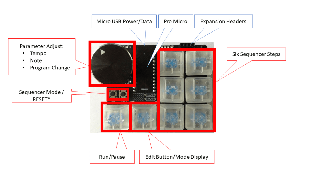
Note that this is prototype hardware and the MODE and RESET buttons are swapped around on the final version of the board.
This is how I’m using the controls:
- The Rotary Encoder is used to change parameters and depending on the mode, this will be one of tempo (in play mode), note (in edit mode) or MIDI Control value (in MIDI control mode).
- The Rotary Encoder’s switch is used to enter and exit MIDI Control mode, which is indicated by the Edit button/Mode display shining white and turning the encoder will result in MIDI program change messages being sent over the configured MIDI channel.
- The Run/Pause switch starts and stops the running of the sequencer and is indicated by the button glowing green or red.
- When running, each of the six sequencer steps will illuminate in turn. If there is no note to be played it will show a low brightness white colour. If there is a note to play it will show the colour associated with that note. If there are notes on both tracks to play it will show the colour of the last track.
- The Edit Button/Mode Display enters edit mode. Press once to enter edit mode for track one and again for edit mode on track two. Keep pressing will alternate between tracks. The button will shine blue for track one and purple for track two.
- When in edit mode for one of the tracks, selecting a sequencer step will start editing the note played on that step for that track. Turn the rotary encoder to change the node. Turning “hard left” back to a red colour is “no note”, but otherwise a range of MIDI nodes between C2 (36) and C6 (84) can be selected. The sequencer will keep running in the background so you can hear how your change is sounding.
- The system will automatically exit edit mode if there is no button pressed or the encoder isn’t turned for five seconds.
The ATmega32U4 based Arduinos can be a bit fiddly to program, so it is really handy having a RESET button. Sometimes you need to double-press RESET at just the right moment to get the upload to actually work – it is a bit of a fine art! But experiment and you’ll get the hang of it – it often takes me several goes.
If you find that the board seems to change COM ports as it switches between the bootloader (required for uploading) and MIDI device (required for functioning) then following the “hack” described here can help a lot.
The Code
I’m not going to go through the code in detail – it is quite complex, being a mix of a number of previous projects as described in the introduction – so this is a fairly high level description.
There are four key functions it is having to perform:
- Scan the button, encoder switch and keys with some suitable “debouncing”.
- Scan and service the rotary encoder.
- Provide feedback via the coloured LEDs.
- Perform the timed sequencer functions outputting over MIDI when required.
The different elements have been split up in the code in what is hopefully a relatively obvious way! We also have to keep track of the “auto time out” for edit mode.
I’m using the following libraries:
- Arduino MIDI Library: https://github.com/FortySevenEffects/arduino_midi_library
- USB-MIDI Library: https://github.com/lathoub/Arduino-USBMIDI
- RotaryEncoder: https://github.com/mathertel/RotaryEncoder
- Adafruit NeoPixels: https://learn.adafruit.com/adafruit-neopixel-uberguide/arduino-library-use
There are many tweakable settings at the top of the file, but be warned, I’ve not tested all variants. Some of the options are fixed (e.g. the pinouts used by the JCProMacroV2) but others are configurable.
Things you can change relatively easily:
- Number of tracks supported (default is two).
- The various colours used for the displays.
- The MIDI channel (default is channel 1).
- The range of tempo supported and the range of MIDI notes.
Things that could be changed if you were more adventurous and wanted to really get into the code:
- The number of steps. It supports six steps as there are six buttons/LEDs but it should in principle be possible to “double up” buttons and LEDs to support, for example, 12 steps.
- Different sequencer modes. There are four coding in at present as follows:
- Normal play.
- Reverse play.
- Double play plays each note twice.
- Random play – chooses a random step each time.
- Add more MIDI control change messages. At present there is only one “control” mode which allows the encoder to send MIDI Program Change messages, but it would be possible to change this for a MIDI CC message or even add selectable modes for the MIDI control mode too.
- Use the expansion headers. The main JCProMacroV2 project supports an I2C OLED display too, which I’ve not used here.
- Add serial MIDI IN functionality and support USB and serial at the same time to give some kind of bi-direction USB to Serial MIDI functionality.
One last thing. I have prototype hardware, so a few of the hardware settings are slightly different from the final “production” version. There is a configuration option at the top to switch over to my prototype hardware, but you can probably ignore that!
5-Pin Serial MIDI
We can’t use the hardware serial ports from the ATmega32U4 as pins 0 and 1 are used for the rotary encoder on this design, but it is possible to drive a serial protocol on a general IO pin using the SoftwareSerial library. Basically the code uses software to drive a pin high or low as required by the serial code. This isn’t particularly quick and uses more of the microcontroller’s processing power for the serial comms than a hardware serial port does, but for the MIDI baud rate of 31250Hz it is very “do-able”.
To set up and use the Arduino MIDI library for Software Serial is a little more complex, but everything you need to know is in the “AltPinSerial” example code. The full initialisation is as follows:
#define MIDI_RX_PIN 6
#define MIDI_TX_PIN 7
using Transport = MIDI_NAMESPACE::SerialMIDI<SoftwareSerial>;
SoftwareSerial swSerial = SoftwareSerial(MIDI_RX_PIN, MIDI_TX_PIN);
Transport serialMIDI(swSerial);
MIDI_NAMESPACE::MidiInterface<Transport> MIDI((Transport&)serialMIDI);
I’ve defined both a RX and TX pin as the interface assumes it, but in this case we’re only using the TX pin. To get the JC Pro Macro 2 talking serial (5-pin DIN) MIDI there are a few options. We can either use one of the Ready-Made MIDI Modules or go for the simplest option of two 220Ω resistors and a 5-pin DIN socket as shown below.
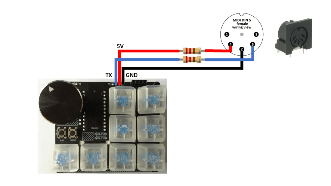
Three is a configuration option at the top of the code to choose between USB and serial MIDI.
Closing Thoughts
This is a great little board. In the video you can see it hooked up via USB to my MT32-Pi in “general MIDI synth mode”. I’ve also had the “real MIDI” hooked up to my real MT-32 module too.
There are a number of “macro pads” around and many are using more powerful processors than the ATmega32U4. But they are often most fully supported using either CircuitPython or Micropython, so its nice for me to be able to (relatively) trivially program one from the Arduino environment. You often don’t find a combination of rotary encoder, clicky keys and expandable IO either.
It should be possible to configure the JC Pro Macro 2 as a MIDI controller for your PC digital audio workstation, but I don’t tend to use one, so I’ve not looked into that yet, but the basics here of using USB MIDI should set you up on that path should you so wish. If someone wanted to let me know which MIDI controllers are useful for such things, I’d be very happy to take a look.
I wish Jeremy well with his Kickstarter campaign!
Kevin
