I found this “Atari Punk Light Theremin” circuit which uses a 556 timer chip but haven’t been able to find out much about it on the Internet … at least under that name…
But I did find quite a lot about the “Atari Punk Console” which appears to have taken on an Internet life of its own. You can read all about it on wikipedia, but it is essentially Forrest Mims’ “Stepped Tone Generator” based on the 556 timer chip. You can read how it all works in Forrest Mims’ own words here.
As for the “Theremin” part, I’m quite a fan of the Theremin and similar instruments, but I’ll leave that discussion for another day…
This isn’t really a beginner project, so if you want something a little more straight forward to get you going, then see the Getting Started pages.
If this piques your interest but you can’t find the exact board I have, then there are several other similar circuits on the Internet if you search for “556 Theremin” or “Atari Punk Console”.
Parts list
- “Atari Punk/Light Theremin” circuit board.
- 9V battery.
- Case and wires.
- Components:
-
1x 556 timer chip
-
2x light dependent resistors
-
2x 1k resistor
-
2x 500k potentiometer
-
1x 5k potentiometer
-
3x switches
-
1x 0.1uf capacitor
-
1x 0.01uF capacitor
-
1x 10uF electrolytic capacitor
-
1x 9v battery clip
-
The Circuit
I’ve not been able to find the exact circuit used here online, but I believe the one shown below matches my circuit board. This compares pretty well with the original “APC” circuit – the original “stepped tone generator”.

There are a few extras on the circuit board I haven’t shown in the circuit:
- The board has an extra 1k resistor and LED, which I’ve not populated. This is just a simple power LED as far as I can see.
- The board has two jumpers for “VCONTORL” that seem to link over to the CV and CV2 pins on the 556. These aren’t used either.
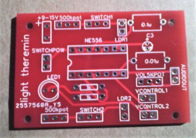
Here is the board itself:
And here it is with everything attached and mounted in a plastic tub.


Things to note while constructing the board:
- All the potentiometers only use two of the three connections, so be sure to check the tracks on the board to get the right ones.
- If you don’t need an on/off switch, you can jumper across those pins.
- I didn’t bother with an LED, but you might see in the photos that I’d already soldered on the associated resistor before deciding not to bother with the LED.
- The two VCONTROL links are not connected to anything.
- I used a socket for the 556 chip as a precaution against my dodgy soldering.
- I bent over the 10uF capacitor prior to soldering so it didn’t sit proud of the board.
- All the components were mounted into the box from the inside out, apart from the two LDRs. These were poked through small holes and then soldered on the inside.
Of course if you build one yourself, feel free to build it as you will.
Operation
This is a pure electronics project and works generally as follows:
- There are two switches to select either potentiometer control or the light dependent resistor. These can be independently chosen.
- It has a volume control, but mine isn’t really working – I haven’t tried to work out why as I just use the jack to plug it into something else.
- It is powered from a 9V battery via an on-off switch.
The two pots interact to change the tones, which are a series of square wave pulses at different frequencies and with different pulse widths.
In the words of the original designer:
“[The stepped-tone generator] produces sounds resembling plucked violin strings to drum as [the potentiometers] are adjusted. Frequency of stepped output decreases in progressively smaller increments as [the potentiometer] is reduced in value.”
It is worth starting it in potentiometer mode to get an idea for how it works before switching over to the LDRs. There are certain “really useful” ranges towards the middle of the pots that generate some of the most interesting noises.
Then switch in one LDR to get a feel for what it does. I found that popping a short bit of un-heated heat-shrink over the LDR makes it less swamped by ambient light, but you’ll need to experiment!
Finally, try both LDRs, but don’t use too sweeping movements. Small movements seem to work best.
Closing Thoughts
It has been interesting to read about the tale of the “Atari Punk Console” and now I understand a little more how my “light Theremin” was meant to work, I think there is some room for experimentation here.
The original author suggests tweaking the values of the fixed resistor and capacitors so that is perhaps a starting point.
It might also be interesting to have some way of “triggering” the circuit too. At the simplest, just a “one-shot” (i.e. non-latching) switch might do it.
I might even breadboard one up from scratch myself, which would be a useful way of double checking that circuit too. I certainly want to find out more about how the inputs to 555 timers work and combine in a 556 to produce this kind of effect.
And I really ought to find it a more dignified enclosure than an old food box!
Kevin
