In the spirit of several of the other microconroller prototyping MIDI boards I’ve already made, this is one for Waveshare Zero format boards.
Warning! I strongly recommend using old or second hand equipment for your experiments. I am not responsible for any damage to expensive instruments!
If you are new to microcontrollers, see the Getting Started pages.
The Circuit
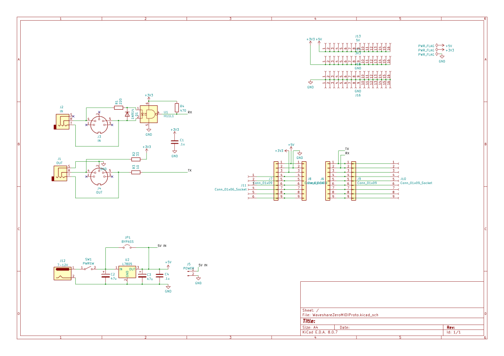
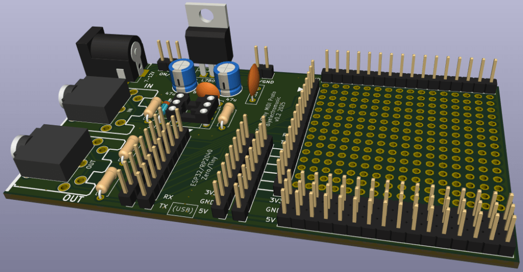
This is essentially a 3V3 MIDI IN/OUT circuit, a 7805 based power supply and headers for the prototyping area and the Waveshare Zero format board itself. I’ve included a solder jumper to allow the bypassing of the regulator if a 5V barrel supply is used instead (this can only be used if no regulator is fitted however).
The Waveshare Zero boards can be powered via 5V directly into the 5V pin.
The only pins on the Waveshare that are connected are the power, GND and RX/TX, as these tend to all be in the same place on these boards (more here: Waveshare Zero, Pimoroni Tiny, and Neopixels). All other pins find their way to headers.
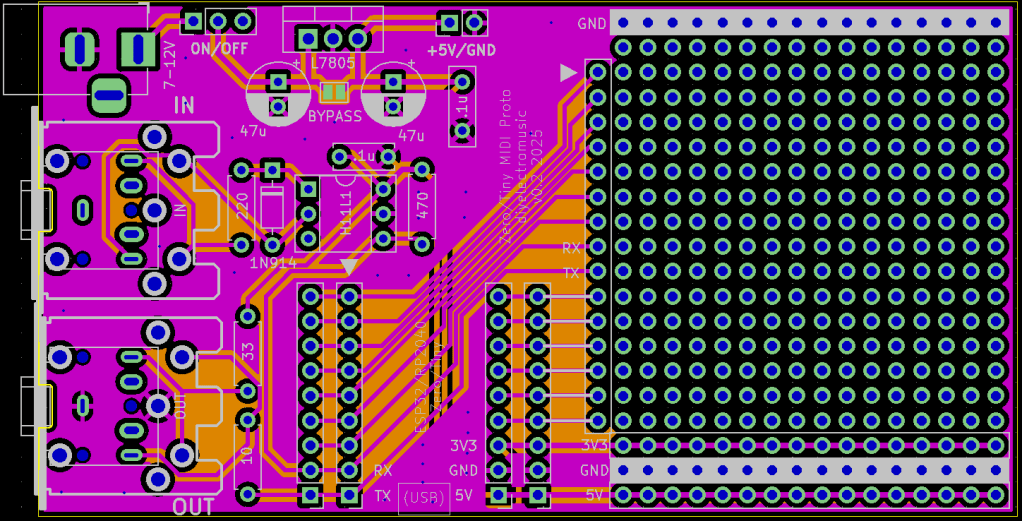
PCB Design
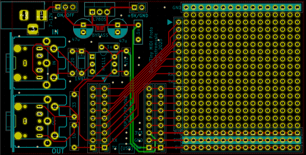
This follows the format of my Nano MIDI Proto PCB Design and my XIAO MIDI Proto PCB.
There are a number of additional breakout header sections for the Waveshare Zero IO pins, plus 5V, 3V3, and GND.
All the power related circuitry is together near the top of the board. It includes a 5V header and an option for direct 5V via the barrel jack, if the regulator is left out. It also includes a 3-pin 2.54mm pitch header which can be used for a power switch for the barrel jack connection.
There are overlapping footprints for MIDI DIN and TRS, so either can be populated.
Closing Thoughts
Annoyingly there were two mistakes in the first version of this PCB:
- The TRS sockets didn’t line up properly over the MIDI sockets.
- The header sockets for the Waveshare Zero were 2.54mm too far apartt.
Both of these could be worked around (mostly), but these issues were fixed in the above versions of the board.
Kevin
