This is another project for my Arduino Clock Generator Shield PCB. This one takes a MIDI clock sync pulse and outputs trigger pulses as required.
Warning! I strongly recommend using old or second hand equipment for your experiments. I am not responsible for any damage to expensive instruments!
If you are new to Arduino, see the Getting Started pages.
Parts list
- Arduino Uno
- Arduino Clock Generator Shield PCB
- Ready-Made MIDI Modules or one of the DIY MIDI Interfaces
- Source of MIDI clock sync pulses
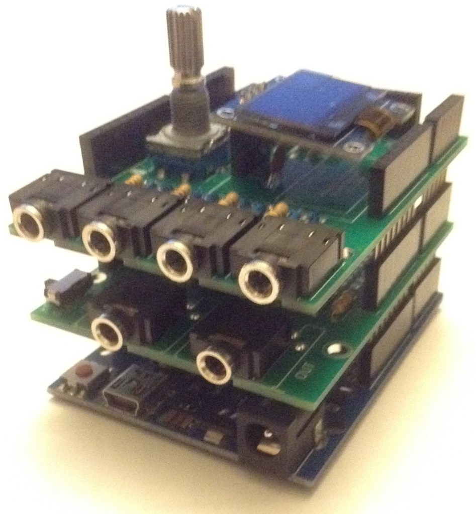
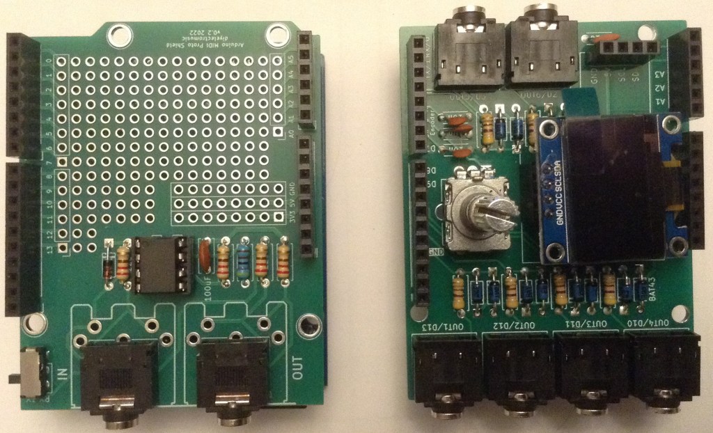
The Circuit
I’ve used my Arduino MIDI Proto Shield and my Arduino Clock Generator Shield PCB, but the Clock Generator Shield could be used with any 5V MIDI IN circuit connected to D0/RX.
The Code
This is a variant of the code I used in Arduino Euclidean Gate Sequencer – Part 3 but rather than an internal clock source and Euclidean divisors, I’m using MIDI as the sync trigger and allowing the number of “parts per quarter note” (ppqn) to be set using the rotary encoder and display.
A MIDI clock pulse runs at 24 ppqn, so there are 24 clock MIDI messages per crotchet. I’ve allowed any divisor of 24 to be used, so the pulses for each of the six trigger channels can be 1, 2, 3, 4, 6, 8, 12 or 24 ppqn based on that MIDI input.
There are actually four MIDI messages that are significant to clocks and timing (well actually there is another one, but I’m ignoring that one for now). These are all in the “system real time” category:
- F8 – MIDI timing clock – sent 24 times per crotchet.
- FA – Start
- FB – Continue
- FC – Stop
The start/continue/stop messages are meant to control a sequencer, with start restarting a sequence from the beginning and continue expecting it to restart from wherever it got to on receiving a stop.
All will be supported in this code, with start resetting all the gate sequences, and continue/stop just pausing and unpausing things.
The core logic will be as follows:
Use encoder/display to set the divisor of 24 to use per channel.
(i.e. choose the ppqn per channel)

Read MIDI

IF MIDI Start: reset gates and enable the clock
IF MIDI Continue: enable the clock
IF MIDI Stop: stop the clock
IF MIDI Clock THEN:
  FOR EACH channel:
    Decrement the channel's counter (based on the divisor)
    IF counter == 0 THEN:
      Set channel output HIGH for 10mS
      Reset the channel's counter to the divisor again
So if the channel divisor is set to 6 (for example) then there will be 6 gates set per every 24 MIDI clock messages received – i.e. a gate signal every 4 MIDI clock messages.
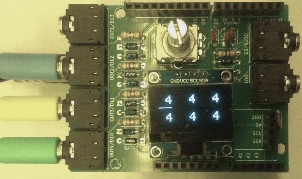
The encoder/display will show each ppqn value for each of the six channels. Pressing the encoder’s switch will move a cursor between each channel and turning the encoder will change the value between the preset options listed above.
Closing Thoughts
The video shows the MIDI clock generator syncing up a drum pattern from my ION iDM02 with three Korg Volcas.
It isn’t perfect – sometimes the Volcas stutter slightly with the timing. I’m wondering if that is because I’m using a 10mS pulse and the Volcas usually use 15mS pulses for their sync.
There is also the weirdness that is the Volcas expecting to play two sequence steps per sync pulse. There are settings to change this – see my Korg Volca Notes, but it does mean that even on the slowest setting of 1 ppqn, the tempo of each step is effectively double whatever the iDM02 is saying.
The consequence of all this is that the Volcas will only really work with ppqn settings of 1 or 2, or maybe 4 (on a good day, with a slow tempo!).
The FM2 seems the most robust. I’ve checked the pulses with an oscilloscope and they seem pretty reliable to me, so I’m guessing there must be some oddity about how the Volcas are reacting to the pulses.
Update: A 10mS or 15mS pulse makes no difference, but if the Volca is configured for a falling edge Sync IN pulse (see my Korg Volca Notes on Sync) then it seems pretty reliable for all three of the Keys, Modular and FM2.
I should try syncing it up with my “Baby8” CV Step Sequencer and see how that goes.
Kevin