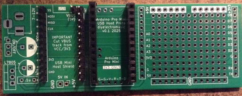
Here are the build notes for my Arduino Pro Mini USB Host Proto PCB.

Warning! I strongly recommend using old or second hand equipment for your experiments. I am not responsible for any damage to expensive instruments!
If you are new to electronics and microcontrollers, see the Getting Started pages.
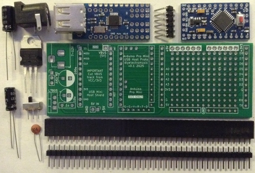
Bill of Materials
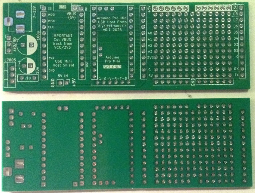
- Arduino Pro Mini USB Proto PCB (GitHub link below)
- Arduino Pro Mini (3V3 version)
- Mini USB Host Shield 2.0
- 2x (or 4x) 12-way pin header sockets
- Pin headers
Power supply (optional):
- 1x 7805 regulator
- 1x 2.1mm barrel jack socket (see photos and PCB for footprint)
- 1x 100nF ceramic capacitor
- 1x 10uF electrolytic capacitor
- 1x 100uF electrolytic capacitor
- Optional: 1x slider switch, PCB mount, 2.54mm pitch connectors
The power supply section can be omitted if the board is to be powered directly off 5V, for which an additional 5V/GND set of pin headers is provided.
Build Steps
There isn’t a particular assembly order for this board, but I built it in the following order:
- Prepare the mini USB Host shield (see below).
- Header pins for the mini USB Host shield.
- Header sockets for the Pro Mini.
- Components for the power supply.
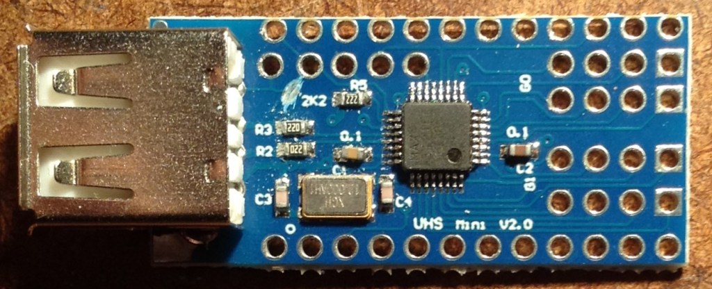
The Mini USB Host shield will probably require a track cutting to isolate VBUS from the 3V3 supply of the Pro Mini. The track in question links the VBUS solder pad to the nearby 2K2 resistor. The track needs to be cut between the pad and the resistor, but care is needed to ensure it isn’t cut on the “USB” side. See photo below.
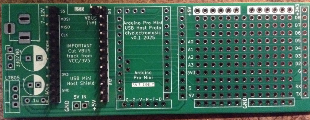
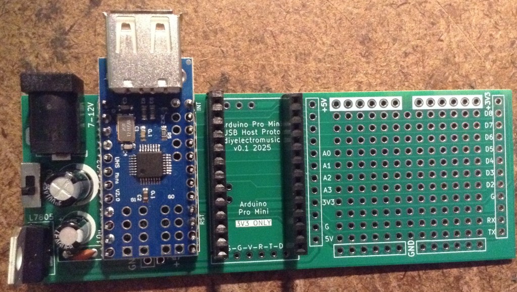
Here are some build photos.
Notice in the above there is an additional single pin for the VBUS connection. I’ve used pin headers rather than a socket to allow me to mount the USB Host shield permanently on the board.
If a socket is used then it will be necessary to find an alternative means to connect the VBUS pad on the shield to the VBUS or 5V connection on the PCB.
I’m not using any headers for the Pro Mini’s programming connection. This doesn’t actually do anything on the PCB and is really just there for helping to orient the board.
In the following, I’ve only actually soldered the pins on the USB Host shield that are used to connect it to the Pro Mini. There are 9 in total, not including VBUS, and all, apart from a second GND, are labelled on the PCB:
- Top four pins on the left (SS, MOSI, MISO, CLK).
- Topmost single pin on the right (IN).
- GND and 3V3 on the left (2nd and 4th from the bottom).
- GND and RST on the right (3rd and 4th from the bottom).

If used, I soldered the power supply components last.
Testing
I recommend performing the general tests described here: PCBs.
Note: when programming the Pro Mini an additional programming header is required.
Some of the cheap programmers do not accurately set the voltage for powering the board, even if there is a switch for 5V/3V3 operation, so it is worth double checking prior to use.
If an external 5V connection is required, the additional GND/5V header pin at the bottom of the USB Host shield can be used.
PCB Errata
There are the following issues with this PCB:
- None at this time.
Enhancements:
- I’ve included a footprint for the programming header, but it doesn’t do anything or go anywhere.
Sample Applications
Here is a simple USB MIDI monitor application that can be used to see if the board is working:

Closing Thoughts
As I say, I’m not sure this will get a lot of use, but it can go in the bits box for a rainy day!
Kevin
