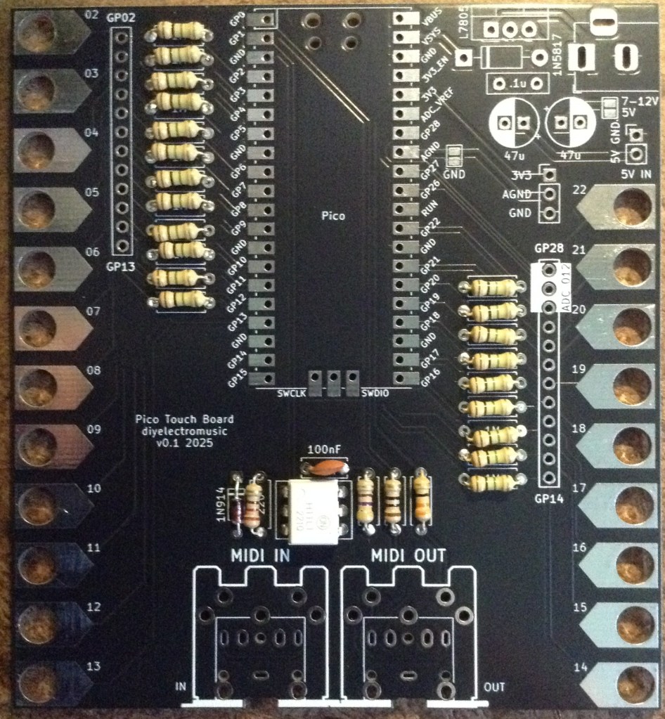
Here are the build notes for my Pico Touch Board PCB.

Warning! I strongly recommend using old or second hand equipment for your experiments. I am not responsible for any damage to expensive instruments!
If you are new to microcontrollers and electronics, see the Getting Started pages.
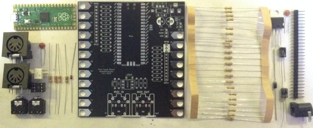
Bill of Materials
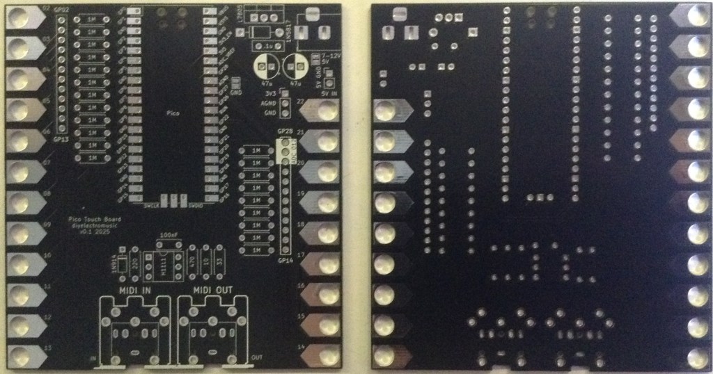
- Pico Touch Board PCB (GitHub link below)
- Raspberry Pi Pico
- 21 x 1MΩ resistors
- Option: 2x 20-way pin header sockets (for the Pico)
- Pin headers or sockets as required
Optional: MIDI Interface:
- 1x H11L1 optoisolator
- 1x 1N4148 or 1N914 signal diode
- 1x 10Ω, 1x 33Ω, 1×220Ω, 1×470Ω resistors
- 1x 100nF ceramic capacitor
- Optional: 1x 6-way DIP socket
- Either 2x 5-pin DIN sockets OR 2x 3.5mm TRS sockets (see photos and PCB for footprints)
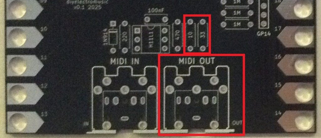
Note: If MIDI OUT only is required, then only the following is required:
- 1x 10Ω, 1x 33Ω resistors
- Either 1x 5-pin DIN socket OR 1x 3.5mm TRS socket
Optional: Power Supply:
- 1x 7508 regulator
- 1x 1N5817 Schottky diode
- 1x 100nF ceramic capacitor
- 2x 47uF electrolytic capacitors
- 1x 2.1mm barrel jack socket (see photos and PCB for footprint)
Build Steps
Taking a typical “low to high” soldering approach, this is the suggested order of assembly:
- All resistors and diode for MIDI interface.
- 1M resistors.
- PSU diode (if used).
- DIP socket (if used) and TRS sockets (if used).
- Disc capacitors.
- Pico header sockets (if used) or Pico (if soldered directly).
- Other PSU components.
- MIDI DIN sockets (if used).
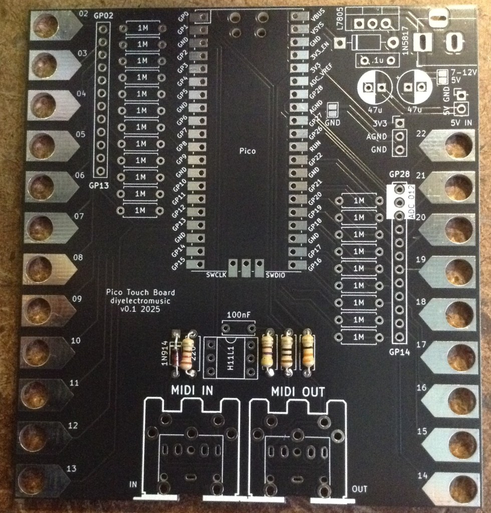
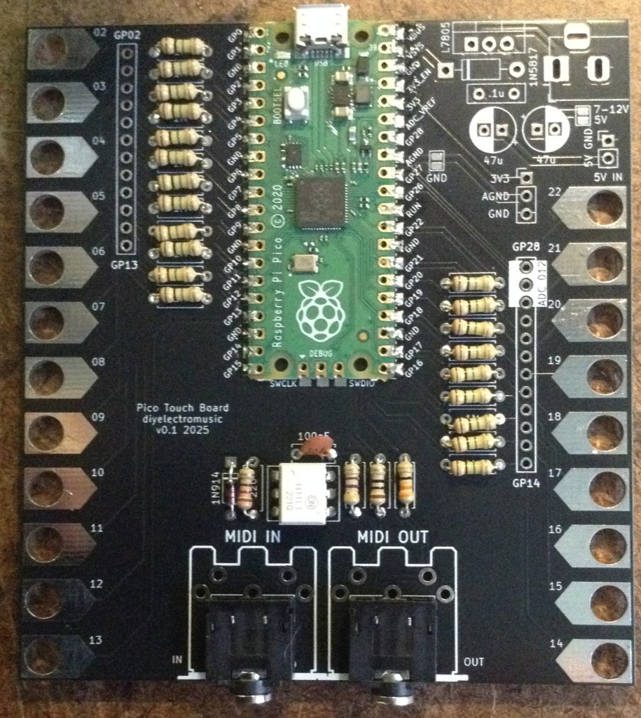
Here are some build photos.
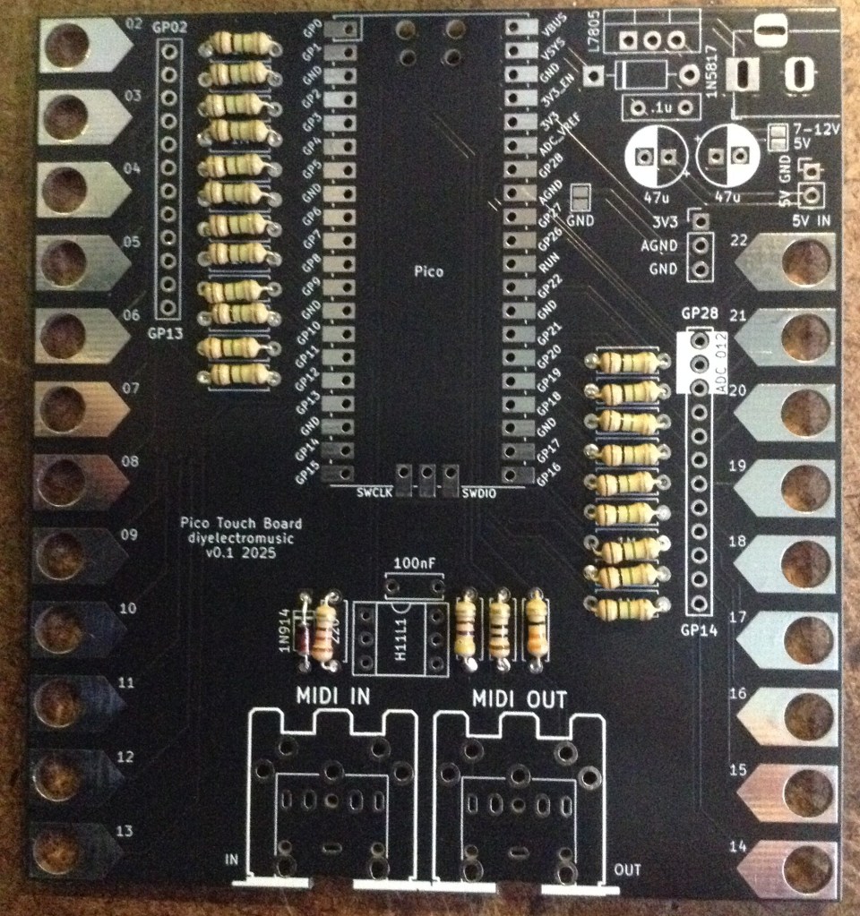
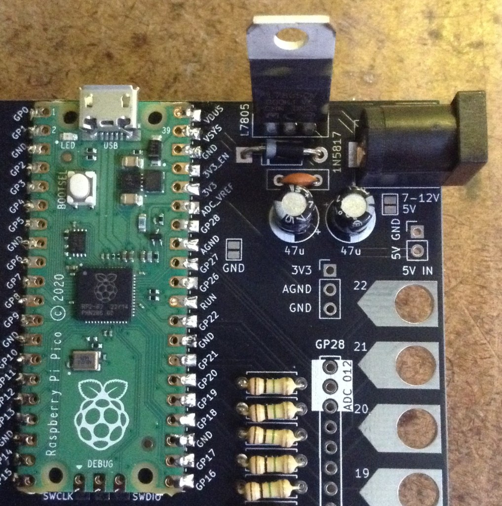
The power supply section, if populated, will look something like this.
Configuration Options
There are three MIDI options:
- Full USB MIDI and serial MIDI. This provides both USB and serial MIDI IN and OUT function and has all MIDI components populated, as shown in the above build photos.
- USB MIDI and serial MIDI OUT only.
- Rely on USB MIDI only. In this case, the whole of the MIDI section at the bottom of the PCB can be omitted.
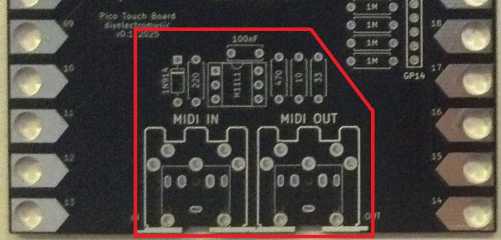
If MIDI OUT only is required then only the highlighted components below are required.
If no serial MIDI is required at all then all the components highlighted below can be omitted.
There are various options related to the power supply.
- Omit it and just use USB. It is entirely feasible to ignore all PSU components and power the board using the Pico’s micro USB. In fact if the board is to be used as a USB MIDI controller then it will be plugged into something else anyway and not powered independently.
- Use the onboard regulator with a 7-12V supply. This is the “all components populated” version. Note that if the provided supply is 9V or greater than it will be quite likely that some kind of heatsink will be required for the regulator.
- Use a direct 5V power supply.
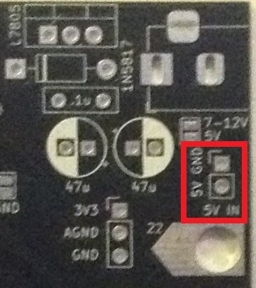
This latter option has a couple of variants, too. One option is to provide a regulated 5V supply directly via the additional “5V IN” header shown below.
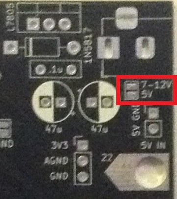
Another option is to bridge the solder jumper marked “7-12V/5V” which bypasses the regulator and allows the use of a 5V regulated supply via the barrel jack directly.
Either way, the key thing is to decide on the power option prior to build and only use one option at a time. In particular if the regulator is installed, neither of the direct 5V power options should be used.
It should be fine to power the Pico over USB if the regulator is present as long as nothing is plugged into the barrel jack at the same time.
Testing
I recommend performing the general tests described here: PCBs.
There are two test Circuitpython programs that can be used to test the board’s operation:
The first piece of code maps each of the 21 GPIO pins/pads onto a MIDI note which is played over both serial MIDI (DIN) and USB MIDI.
The second piece of code is a simple MIDI monitor that prints to the console and lights up the onboard LED when a MIDI note is received.
By default is works for USB MIDI, but the following lines should be uncommented to switch to using serial MIDI to test the touch board.
#midi = adafruit_midi.MIDI(midi_in=usb_midi.ports[0])
uart = busio.UART(tx=board.GP0, rx=board.GP1, baudrate=31250, timeout=0.001)
midi = adafruit_midi.MIDI(midi_in=uart)
PCB Errata
There are the following issues with this PCB:
- None at this time.
Enhancements:
- It might have been nice to have included the footprints for a PWM output filter circuit.
Sample Applications
The provided MIDI test code is already a useful application in its own right – it sends a MIDI note in response to a pad being touched. Other applications will come along in the future. Watch this space.
New applications can be written using Circuitpython’s touchio module and the adafruit_midi library. Note: touchio is availably by default but adafruit_midi needs to be copied into the lib directory from the Circuitpython library bundle.
Closing Thoughts
This seems to work really well. The Circuitpython touchio library means this is very straightforward to use.
And the LEGO-compatible hole spaces has some really interesting possibilities!
Kevin

Kevin, I would like to have a pico touch board that supports 64 touch keys (or just over five octaves) which is very standard for synths keyboards. Could you diagram the circuit design ?
Thanks, Tom
LikeLike
Most keyboards would use a matrix approach, so I’m not clear how that could be done with something like this. There might be a couple of approaches though.
One would be to use several of these. These support 21 keys each, so that could be covered by three of these (an extra GPIO on one of them could be found by using GP1 maybe instead of using it for RX) with a different MIDI starting note and some MIDI merging. I’d probably use a fourth Pico for the MIDI merging so that it stays responsive.
Another approach would be to cascade several MPR121 modules to a single microcontroller.
Another possibility might be to use those TTP223 based modules I wrote about recently. They output a single IO HIGH/LOW so could probably be scanned either in a matrix format or via a shift register.
Those are the kinds of approaches I’d be thinking about (there are articles about most of those tucked away on my blog somewhere).
Kevin
LikeLike
Thank you! I’m having trouble. I installed the latest CircuitPython 10.0.3 and dragged the libraries to the lib folder but it does not show up as a midi device. It keeps blinking the led periodically. I tried older bootloaders but the behavior is the same.
LikeLike
It sounds like it perhaps isn’t running your own code by default.
You have to save your file as code.py or main.py (if I recall correctly) for the code to autorun on power up. Have you tried that?
Kevin
LikeLike
Thank you. Yes, I have it named code.py and also included the adafruit_debouncer,mpy and adafruit_midi (folder) to the lib (folder). I tested it with adafruit-circuitpython-[…]9.2.9.uf2 & adafruit-circuitpython-bundle-9.x (and the latest bootloader & libraries. The results are the same.
LikeLike
Ah! Added adafruit_ticks.mpy to the library and got it working. Thanks!
LikeLike
Ah great! Well done for spotting it 🙂
Kevin
LikeLike