As I was browsing around I happened to notice a couple of interesting add-on boards that comprise a OLED display, rotary encoder and some buttons.
With the addition of a I2S DAC (or just using the existing PWM output) these make a really interesting option for MiniDexed IO.
Warning! I strongly recommend using old or second hand equipment for your experiments. I am not responsible for any damage to expensive instruments!
If you are new to microcontrollers and single board computers, see the Getting Started pages.
The Displays
There are lots of cheap display boards out there. These are the boards I’ve been looking at:
Which are called some variation of the following:
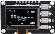
- “0.96 inch OLED IIC 12864 OLED Display with 4×4 key I2C SSD1315 LCD Screen”.
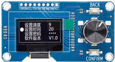
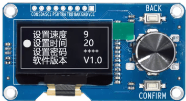
- “1.3 inch OLED display screen with EC11 rotary encoder module IIC”.
- “0.96 inch OLED display screen with EC11 rotary encoder module IIC”.
These particular ones have the following display parameters
SH1106 (1.3″), SSD1306 (0.96″), and SSD1315 (0.96″ with buttons).
| 1.3″ Encoder Display | 0.96″ Encoder display | 0.96″ button display |
| SH1106 | SSD1306 | SSD1315 |
| 128×64 | 128×64 | 128×64 |
| 2 Buttons | 2 Buttons | 4 Buttons |
| Switched Rotary Encoder | Switched Rotary Encoder |
SSD1306 is directly supported by MiniDexed, but the other two are not. But it turns out that the SSD1315 display works fine as a SSD1306 and all three have the same I2C addressing scheme – 0x3C is the default.
The SH1106 based display however will need some updates to the core operating environment used by MiniDexed before it can be used, so for now that one can’t be used.
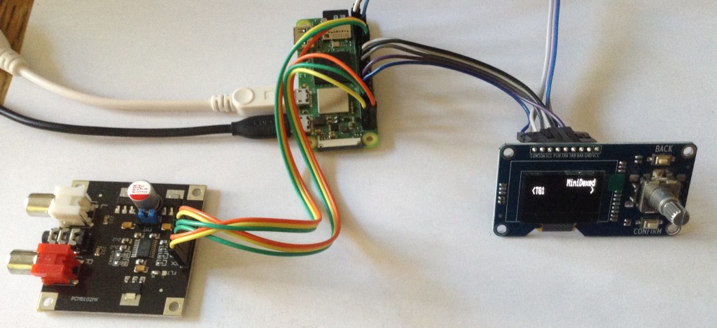
0.96″ Encoder Display
The following wiring and configuration should allow the use of this display with MiniDexed.
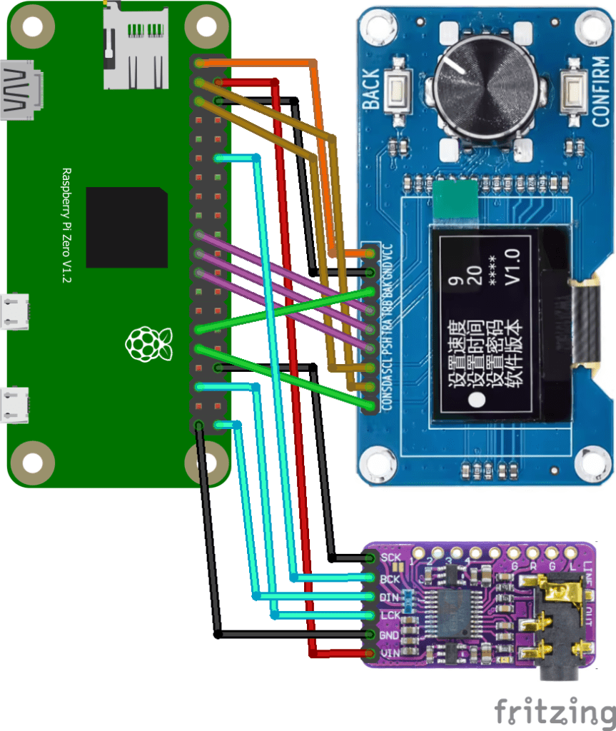
Raspberry Pi GPIO Connections
| Display VCC | 3V3 | 5V | |
| Display SDA | GPIO 2 SDA | 5V | DAC VIN |
| Display SCL | GPIO 3 SCL | GND | Display GND |
| GPIO 4 | GPIO 14 TXD | ||
| GND | GPIO 15 RXD | Opt: MIDI IN | |
| GPIO 17 | GPIO 18 PCM CLK | DAC BCK | |
| GPIO 27 | GND | ||
| GPIO 22 | GPIO 23 | ||
| 3V3 | GPIO 24 | ||
| Display TRB | GPIO 10 | GND | |
| Display TRA | GPIO 9 | GPIO 25 | |
| Display PSH | GPIO 11 | GPIO 8 | |
| GND | GPIO 7 | ||
| ID_SD | ID_SC | ||
| Display BAK | GPIO 5 | GND | |
| Display CON | GPIO 6 | GPIO 12 | |
| GPIO 13 | GND | DAC SCK / GND | |
| DAC LRCK | GPIO 19 PCM FS | GPIO 16 | |
| GPIO 26 | GPIO 20 | ||
| DAC GND | GND | GPIO 21 PCM DOUT | DAC DATA |
Note: I ended up swapping TRA/TRB over (which can be done either in the wiring or in the definitions in minidexed.ini) to make the encoder operate in the direction I wanted.
I’ve also chosen to wire the “CONFIRM” button as a HOME button, but this could be used for SELECT if required. I’m using the encoders switch for SELECT.
The display board doesn’t include any audio so a I2S DAC is highly recommended, which has to be connected separately. It is also possible to connect up a MIDI IN circuit to GPIO 15 (RXD) if required.
MiniDexed.ini Configuration
SoundDevice=i2s

LCDEnabled=1
SSD1306LCDI2CAddress=0x3C
SSD1306LCDWidth=128
SSD1306LCDHeight=64
ButtonPinBack=5
ButtonActionBack=click
ButtonPinSelect=11
ButtonActionSelect=click
ButtonPinHome=6
ButtonActionHome=click
EncoderEnabled=1
EncoderPinClock=10
EncoderPinData=9
It is possible to leave SSD1306LCDHeight=32 and then the display is double-height, but it is also a little grainy, so I prefer just to use half the display with a “fuller” text myself.
Note: my display came with a knob for the encoder that was slightly too tall. When fully pushed on, it stopped the encoder’s switch from working properly!

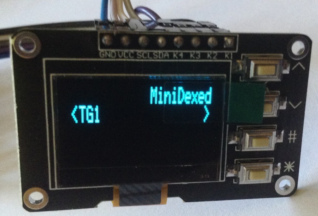
0.96″ Button Display
Here is how to use this display with MiniDexed.

Raspberry Pi GPIO Connections
| Display VCC | 3V3 | 5V | |
| Display SDA | GPIO 2 SDA | 5V | DAC VIN |
| Display SCL | GPIO 3 SCL | GND | Display GND |
| GPIO 4 | GPIO 14 TXD | ||
| GND | GPIO 15 RXD | Opt: MIDI IN | |
| GPIO 17 | GPIO 18 PCM CLK | DAC BCK | |
| GPIO 27 | GND | ||
| GPIO 22 | GPIO 23 | ||
| 3V3 | GPIO 24 | ||
| Display K1 | GPIO 10 | GND | |
| Display K2 | GPIO 9 | GPIO 25 | |
| Display K3 | GPIO 11 | GPIO 8 | |
| GND | GPIO 7 | ||
| ID_SD | ID_SC | ||
| Display K4 | GPIO 5 | GND | |
| GPIO 6 | GPIO 12 | ||
| GPIO 13 | GND | DAC SCK / GND | |
| DAC LRCK | GPIO 19 PCM FS | GPIO 16 | |
| GPIO 26 | GPIO 20 | ||
| DAC GND | GND | GPIO 21 PCM DOUT | DAC DATA |
As there are only four buttons, I’m mapping them to Next, Prev, Select and Back.
This is the minidexed.ini configuration.
SoundDevice=i2s

LCDEnabled=1
SSD1306LCDI2CAddress=0x3C
SSD1306LCDWidth=128
SSD1306LCDHeight=64
ButtonPinPrev=10
ButtonActionPrev=click
ButtonPinNext=9
ButtonActionNext=click
ButtonPinBack=5
ButtonActionBack=click
ButtonPinSelect=11
ButtonActionSelect=click
EncoderEnabled=0
The rotary encoder is on by default, so needs turning off.
Closing Thoughts
I was hoping to be able to get all three up and running, but although the third display is recognised and can be poked to some degree, at the moment it is just showing a garbled output. I suspect it will need some alternative mappings or something.
It was nice to see that the ssd1315 just worked as is.
I notice that MT32-Pi has support for SH1106 and it seems like a relatively thin layer on top of the core SSD1306 support, so I’ll take a look and see if I can get this into circle in a useful way. It would certainly be nice to be able to add support for more displays in MiniDexed.
Kevin

This is great. What would be useful is a board that integrates a display, buttons and encoder and a DAC with output jack and that is designed as a HAT for Raspberry. Plug and Play…
Here’s a nice HAT example (with color display), but it lacks the encoder https://shop.pimoroni.com/products/pirate-audio-line-out?variant=31189750546515
LikeLike
Well that is kind of the approach I’ve taken in my own MiniDexed PCBs (which include MIDI too), but they don’t follow the HAT standard.
But then I don’t really see the point of the HAT standard when not using Raspberry Pi OS as it is all about OS plug-and-play and MiniDexed on circle doesn’t have that anyway.
(Pirate audio is supported now – that was what prompted me to add ST7789 display support…)
Kevin
LikeLike
Hi Kevin,
Nice write up.
Need to also change these lines in the minidexed.ini if not already to
LCDColumns=20
LCDRows=4 (or 2)
otherwise the text is a bit off because it may think it is 16 Columns by default.
I had the same knob problem, I just put a piece of plastic under the cap where the shaft goes, about 1-2mm to give it enough clearance to click, the bottom of the knob was hitting the top of the encoder.
Fred
LikeLike
Great thanks for that – yes, I often forget I’ve changed the columns/rows as I’m often using 20×2 displays by default!
Kevin
LikeLike
Hi,
Thanks for all the information. I had bought the 1.3″ unit and experienced the garbled display. I have not bought the smaller unit. I used your .ini details and the display works but it seems shifted over to the right of it’s screen so the line wraps around to the next line down. Also at the end of the line (after the >) is always shown f8f4
I haven’t put the A/D converter on yet as I just wanted to see if the display would work. This is running on an pi zero.
I built a version on a pi 3 with the standard display and that works really well.
Any ideas?
Regards,
Doug
LikeLike
There is another comment here about setting the rows/columns for the display that I forgot to mention (and need to go back to having a look at). Does that help at all?
Kevin
LikeLike
I’ve had another quick look at this. I’m using the 0.96″ unit and it basically works the same as those smaller ssd1306 displays fine. Are you using the 0.96″ or 1.3″ unit – I wasn’t quite clear? The larger unit is using a chipset that isn’t supported yet.
Kevin
LikeLike
Hi,
I originally bought the 1.3″ and that was totally garbled. Then I found this article and bought the smaller one. I have now built a wiring loom and added an A/D card but still get the same result.
I got the latest release from Git and burned a new SD card. I retained my original .ini file all the same but the suffix code changed to a9d3a6
I changed the SSD1306LCDColumns=16 but it made no difference
a9d3a6
Thanks for your help.
Regards,
Doug
LikeLike
I’m not sure what else to suggest then I’m afraid. Do you have another microcontroller you could try driving the display to make sure it isn’t faulty? I wonder if something like one of the independent graphics libraries for Arduino might be able to interogate the driver chip to see what is installed on your display?
Those would probably be my next two steps – to try to get some more info about what is going on…
Kevin
LikeLike
Thanks!
Going on hols for a week now. I’ll start again when I get home.
Regards,
Doug
LikeLike