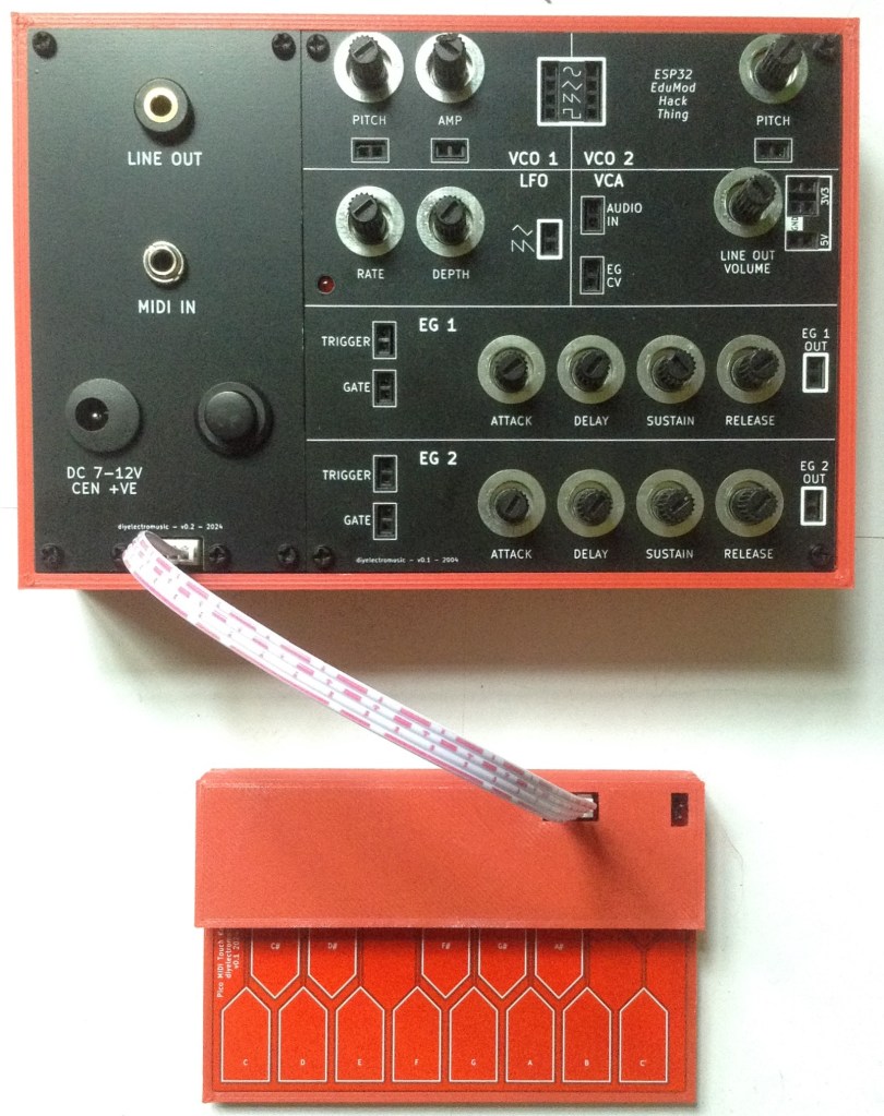
Ok, so this is yet another final, “final” part, but having produced my Raspberry Pi Pico MIDI Touch Keyboard PCB I wanted to show how it could be hooked up to my Educational DIY Synth Thing.
This includes a variant of the accessories panel that supports a connector for the Pico touch keyboard.
- Part 1 – This introduction and high-level design principles.
- Part 2 – Detailed design of an ESP32 based PCB.
- Part 3 – Software design.
- Part 4 – Mechanical assembly and final use.
- Part 5 – Six simple experiments to try.
Optional additional things to try:
- Part 6 – Testing it out with other synth kits.
- Part 7 – Integrating it with my Raspberry Pi Pico MIDI Touch Keyboard.
Warning! I strongly recommend using old or second hand equipment for your experiments. I am not responsible for any damage to expensive instruments!
If you are new to electronics, see the Getting Started pages.
Independent Connections
The first option is to power the Pico via its own USB connector and just use a 3.5mm stereo jack to jack cable for the MIDI connection between the Pico’s TRS MIDI OUT and the Synth Thing’s TRS MIDI IN.
This is probably the simplest way to connect the two devices and in this manner it is no different to attaching any other MIDI controller via TRS MIDI to the Synth Thing.
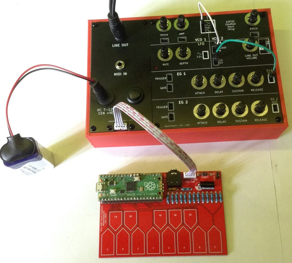
Synth Thing’s Power
The second option is to use the Synth Thing’s 5V output and the MIDI input as shown below.
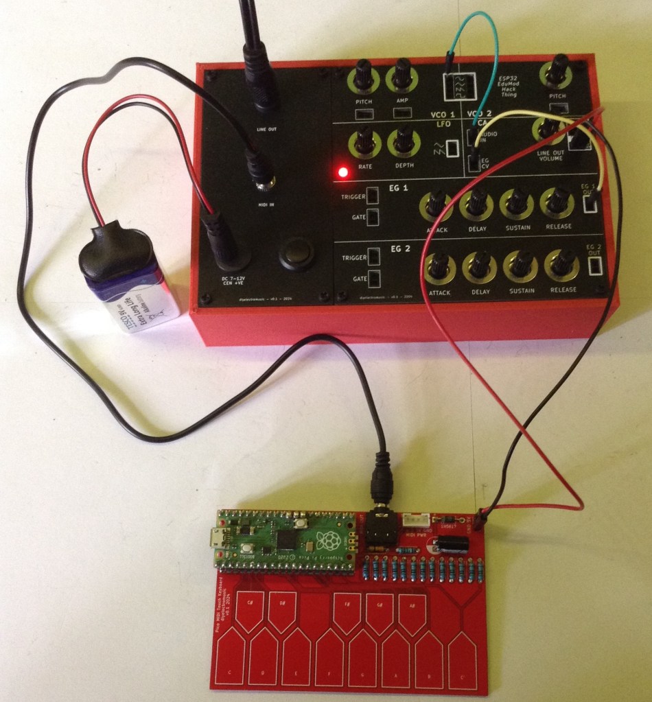
Here the 5V output powers the Pico keyboard directly but the MIDI connection is still provided by the two TRS sockets.
Integrated Synth Thing Panel
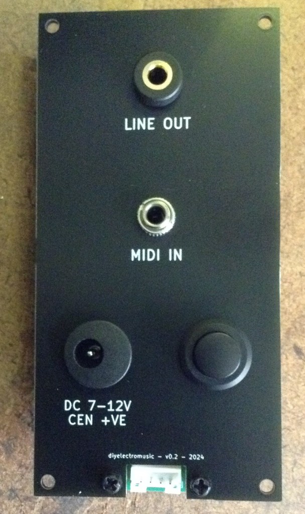
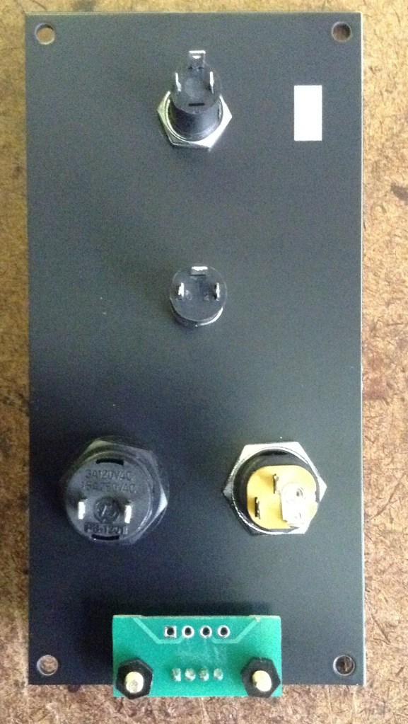
The final option uses an updated Synth Thing accessories panel to provide a JST SH connector compatible with that on the Pico touch keyboard.
The idea is to include a JST SH connector accessible at the bottom of the panel to allow a single 4-way JST SH jumper cable to link the Synth Thing to the Pico keyboard.
The pinout of the JST SH socket will match that on the Pico Keyboard and includes power and MIDI. The pins are (from left to right, looking from the top):
- MIDI Pin 4 – MIDI Pin 5 – 5V – GND
Note: MIDI cannot be used via the TRS and JST SH connectors at the same time!
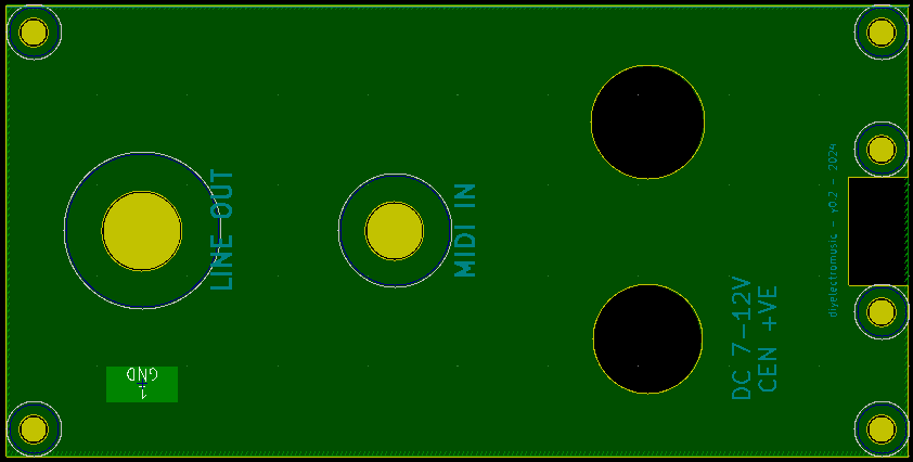
I’ve also taken this opportunity to fix a few niggles with the original panel – the font sizes and I remember to change the hole for the power switch to a 12.5mm diameter hole.
A small breakout board is required for the JST SH connector to allow it to be mounted on the panel.
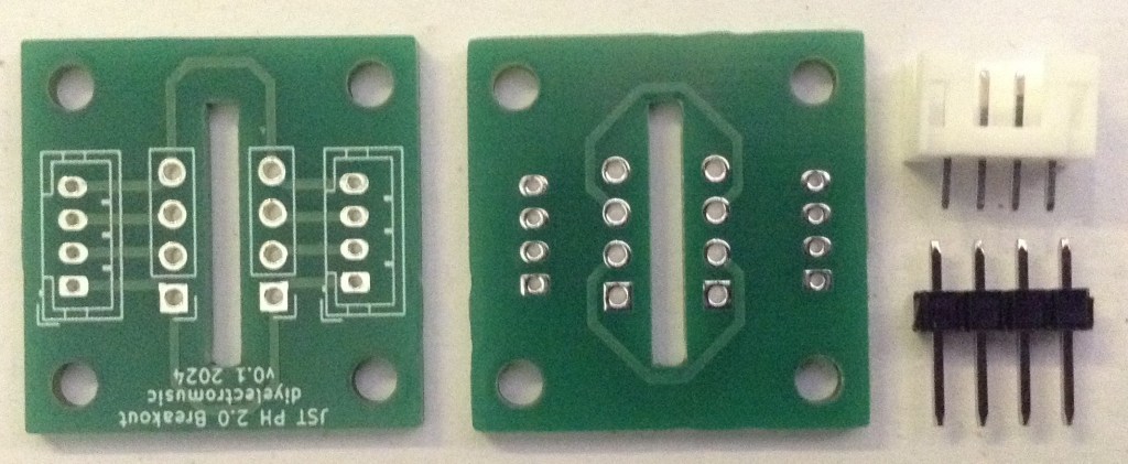
This PCB is actually two breakout boards supporting the mounting of the connector in either orientation. It needs to be cut into two and the JST SH soldered on.
To construct the panel is largely a repeat of the previous process, but now there are some additional connections required to the JST connector.
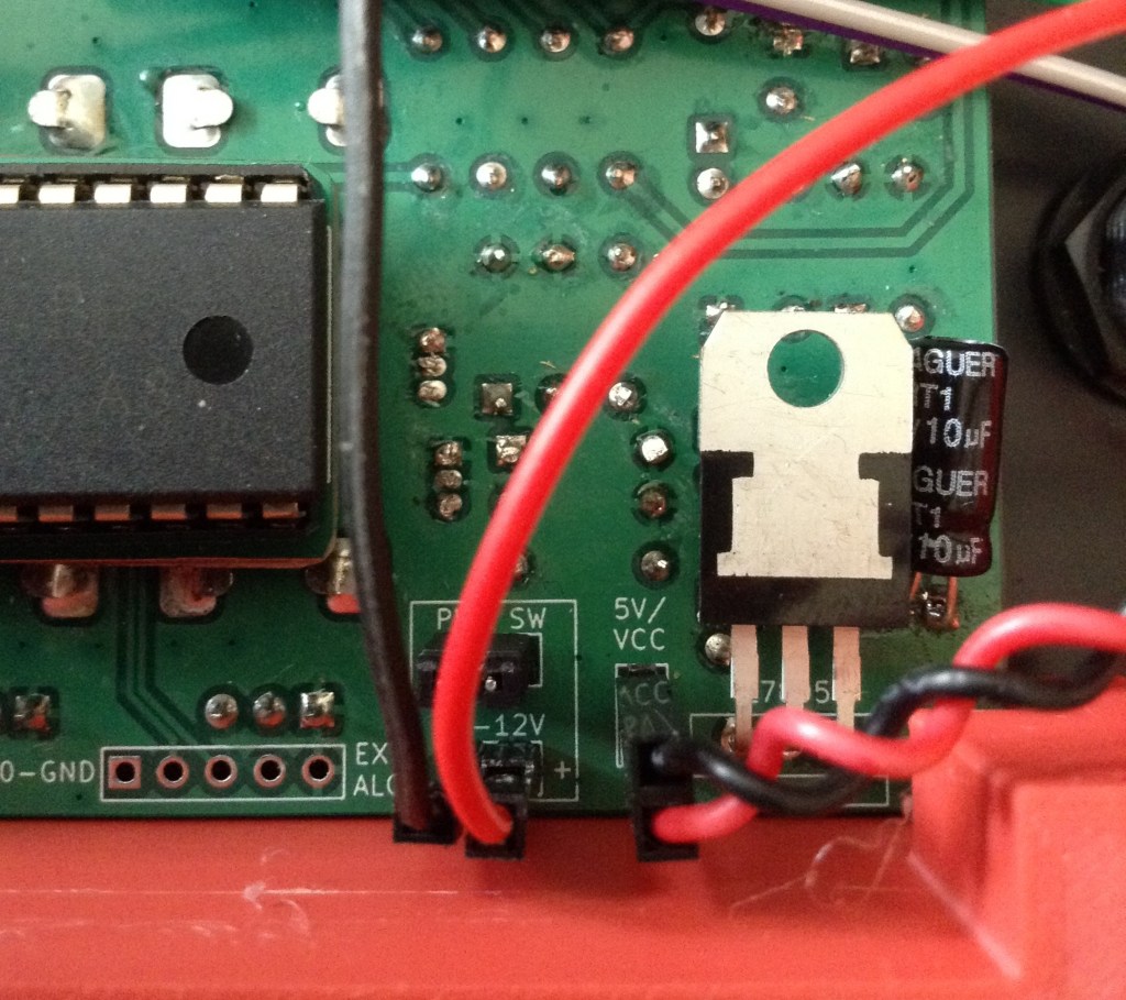
One of those is a 5V power link. The easiest way to access that from the Synth Thing main board is via the 5V-VCC jumper headers, so I’ve soldered up a simple cable with two jumper header socket on one end and a link to the JST SH breakout 5V at the other.

The breakout requires 4mm M2.5 spacers. It also requires a couple of small screws. I only had 6mm screws so ended up trimming the ends off. I didn’t have any nylon 4mm spaces so had to use brass, but I’d have used black nylon if I had them.
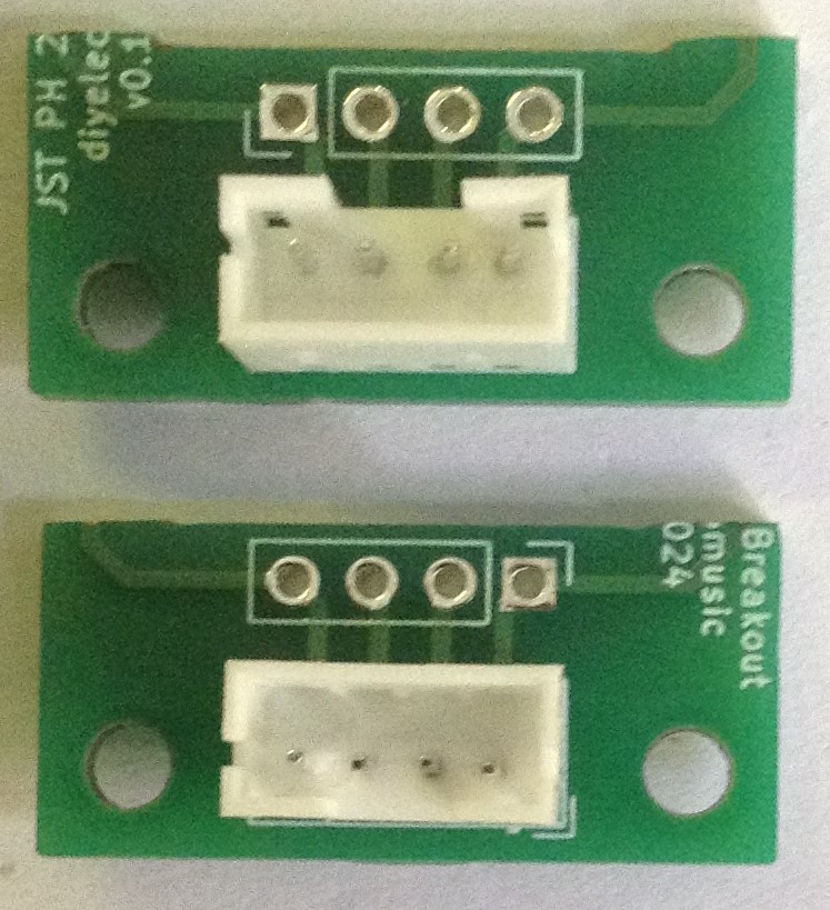
The breakout requires a tap into the MIDI connections, 5V (as mentioned previously) and GND.
Looking from the back, the order (from left to right) is: GND-5V-MIDI 5-MIDI 4.

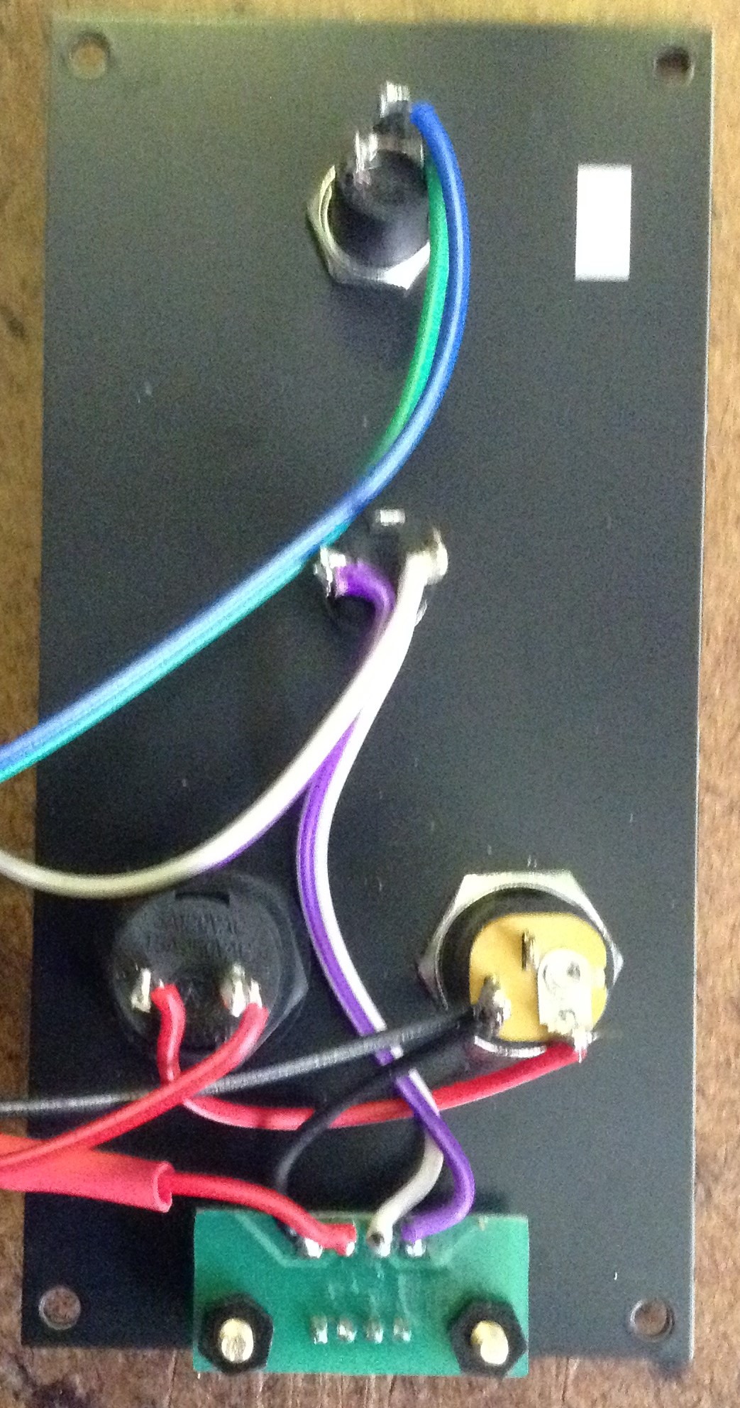

The JST SH connectors are meant to interlock with each other, so they don’t come apart so easily. For the Synth Thing end of the connector wire, I’ve cut off the interlocking lugs to make it easier to pull off.
The files for the new panel and the JST SH breakout have been added to the GitHub repository.
Closing Thoughts
The updated panel makes for a really neat “all-in-one” connection to the keyboard.
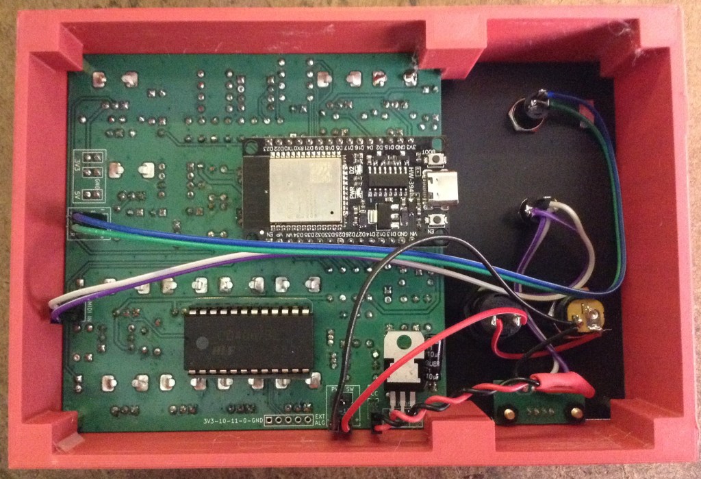
I’ve added a simple 3D printable case, which is very in keeping with the design of the Synth Thing too.
Kevin