It’s been a while since I last played with Pico capacitive touch, but I was always planning on combining it with my touch keyboard PCB to create a self-contained MIDI controller.
I’ve taken the opportunity to build something that I hope to be able to use with my Educational DIY Synth Thing.
Warning! I strongly recommend using old or second hand equipment for your experiments. I am not responsible for any damage to expensive instruments!
If you are new to microcontrollers, see the Getting Started pages.
The Circuit
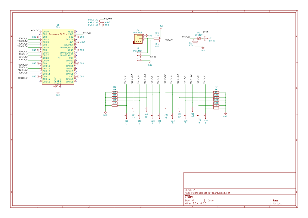
This is using the “one resistor” design from the Raspberry Pi Pico Capacitive Touch project coupled with a simple (unbuffered) 3V3 compatible MIDI OUT interface.
I wanted the board to have several options for power, so have used the recommended Raspberry Pi Pico External Power design (as per the Pico datasheet) which recommends using a Zener diode between the external power source and the VSYS line. This means that if USB power and external power happens to be used at the same time, then they won’t clash and cause a problem.
There is no onboard power regulation, so power options are limited to the 2.3V to 5.5V specified in the datasheet for use with VSYS.
I’ve included a 4-pin connector to breakout the MIDI links and power to allow a single (4-wire) cable to be used to connect to the board.
MIDI is connected to UART 0 TX on GP0. The touch pads are connected to GP2 to GP14.
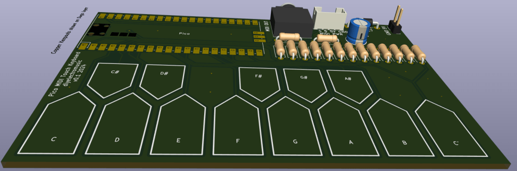
PCB Design
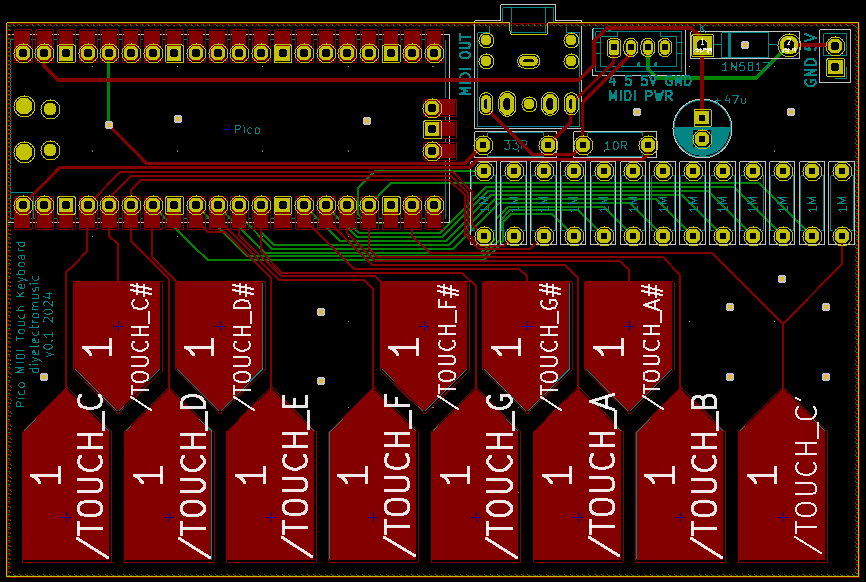
I’m using the same custom pads I used before for the keyboard itself.
All the GPIO pins being used are on the same side of the Pico, so that leaves the option of somehow connecting up to any of the others along the long side of the PCB if required.
I’ve used a JST PH 4-pin (2.0mm pitch) connector for the MIDI/PWR link – mirroring the kind of idea used with Stemma/QUIK/Grove connectors (but sticking to standards). This will take 5V/GND to the board and the MIDI link back out.
Note that the MIDI link is after the MIDI circuit so is meant to connect to a proper MIDI IN circuit. It is not just a link from the UART TX pin.

Closing Thoughts
My thinking with the 4-pin connector is that I might be able to use it as an “all in one” link back to my Educational DIY Synth Thing.
Alternatively a standard 3.5mm jack to jack lead can provide the MIDI link and the board can either be powered via USB (via the Pico) or from the 5V jumper headers of my synth.
Kevin

Any chance u can make one with CV (GATE AND V/OCT) instead or plus of MIDI ?
LikeLike
That isn’t so easy to do with a 3V3 microcontroller as it really needs additional electronics to scale the 0..3V3 range over to something more useful for CV (at least 5V). It would also require either a DAC or PWM filter circuitry on the CV output as the Pico doesn’t have an in-built DAC itself.
It is all possible, but it is a fair bit more complicated on the electronics side, and I’m not really an electronics person 🙂
Kevin
LikeLike