Here are the build notes for my Pico MIDI “Pack” PCB Design.
Warning! I strongly recommend using old or second hand equipment for your experiments. I am not responsible for any damage to expensive instruments!
Bill of Materials
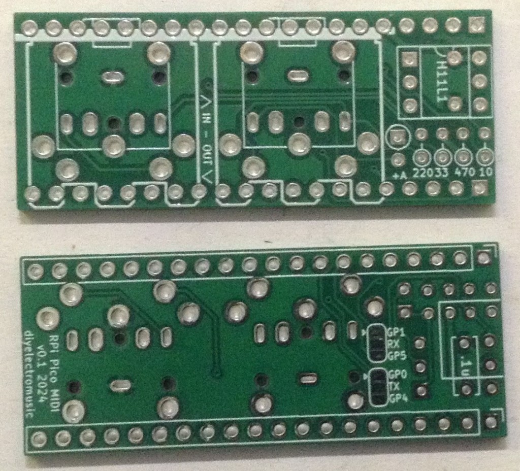
- PCB link (GitHub link below)
- 1x H11L1 optoisolator.
- 1x 1N914 or 1N4148 signal diode.
- 1x each of 10Ω, 33Ω, 220Ω, 470Ω resistors.
- 1x 100nF ceramic capacitor.
- 1x 6-way DIP socket (optional, but recommended).
- 2x 20-way pin header sockets.
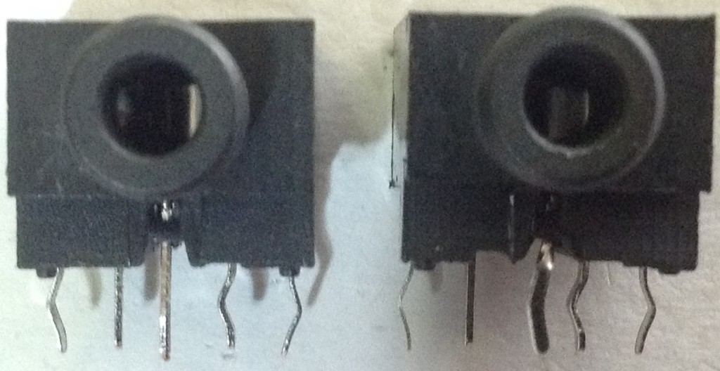
- 2x 5-pin 180 DIN sockets or 2x 2.5mm stereo TRS sockets.
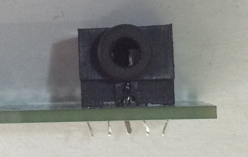
In order to have the sockets fit on the PCB it is important to be using the right physical type. The DIN sockets (if used) must be the type without additional plastic casing over the 5 rear pins. The TRS sockets (if used) have to be raised from the PCB.
The photos below show the different types:
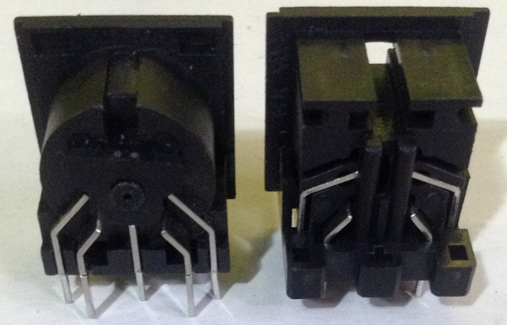
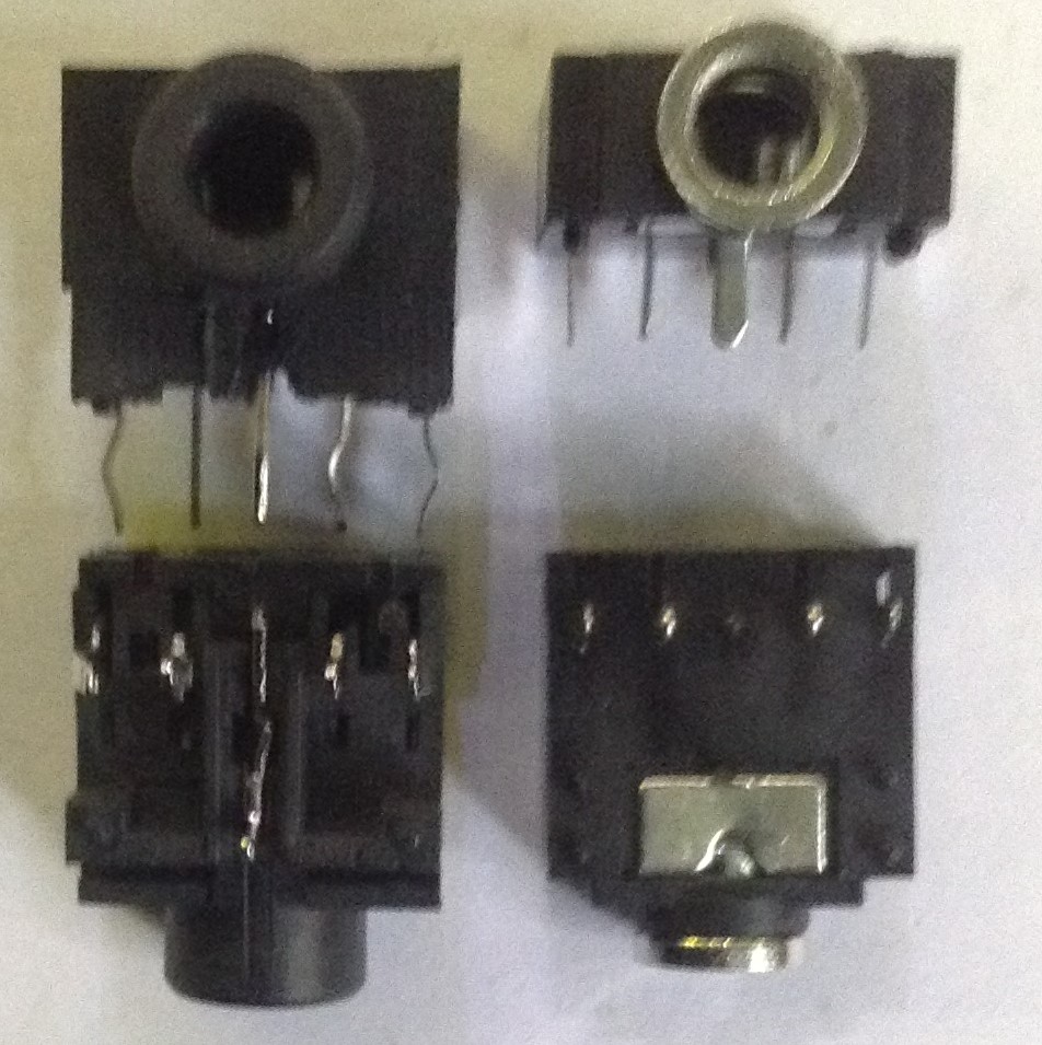
In each case the required sockets are shown on the left and the more typical sockets I’ve used in the past are shown on the right.
Build Steps
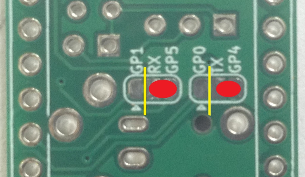
First, if UART 1 operation is required (GPIO 4/5) then the solder bridges must be cut and re-soldered as shown below (cut in yellow, new solder blob in red):
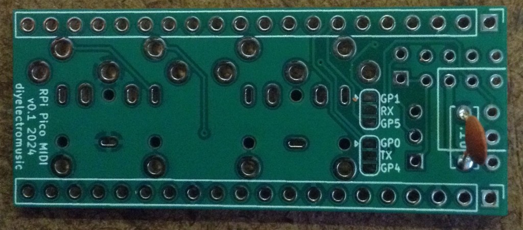
Once that is decided, this is the suggested order of assembly:
- Ceramic capacitor (on the back).
- DIP socket (if used).
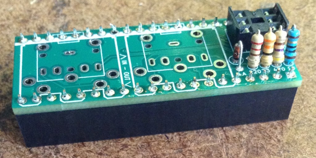
- All resistors and diode.
- 20-way pin-headers.
- DIN or TRS sockets.
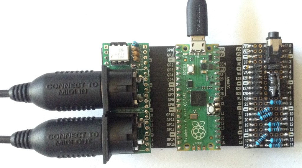
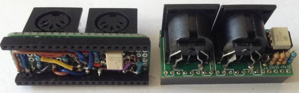
Here are some build photos.
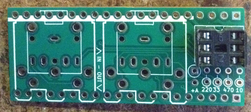
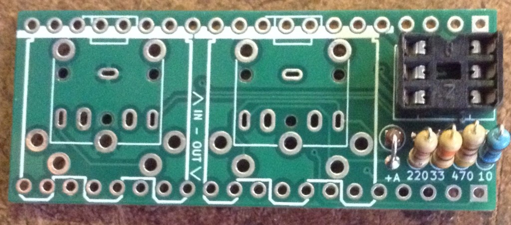
Note that the diode is “stripe side down” when oriented as shown. The “A+” shows which connection is the anode.
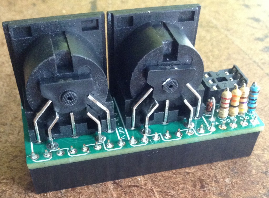
I was pleasantly surprised that the DIN sockets actually fit. I was wondering if I would have to get a craft knife out and trim them off a little, but they seem fine.
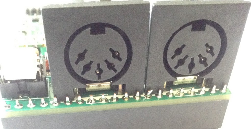
Unlike my soldering – I went and fixed that joint after taking this photo!
If using the TRS sockets, there is one adjustment required. The footprint for the TRS socket assumes a flat GND pin so has a flat hole in the PCB. Unfortunately these raised sockets, whilst still having a flat GND pin, have it rotated through 90 degress.
Consequently it is necessary to rotate the pin to fit the PCB as shown below.
Testing
I recommend performing the general tests described here: PCBs.
MIDI operation can be checked using the following:
- MIDI, MicroPython and the Raspberry Pi Pico – for MIDI OUTPUT.
- MIDI In for 3.3V Microcontrollers – use the simpleMIDIMonitor for MIDI INPUT.
PCB Errata
There are the following issues with this PCB:
- Just the issue with the GND hole of the TRS sockets so far.
Closing Thoughts
Once again I’ve fallen foul of not anticipating that if there is more than one way to do something, then in tech and electronics, of course, there will be options that have opted for the different choices. But that GND pin footprint is pretty minor really.
I’m really pleased this worked. I really wasn’t expecting everything to fit!
And of course, it is a huge improvement on the protoboard version.
Kevin

What can you do with this?
LikeLike
It’s a MIDI interface for the Raspberry Pi Pico – more in the link to the design post, and more in the posts linked from that. So it really depends on what the Pico is programmed to do – this is just the hardware.
But if the words “MIDI interface for Raspberry Pi Pico” don’t mean anything to you, then it’s probably not something you’d find useful 🙂
Kevin
LikeLike
I think I found the answer I was looking for. You can run Dexed on a Pico. https://github.com/diyelectromusic/picodexed
LikeLike