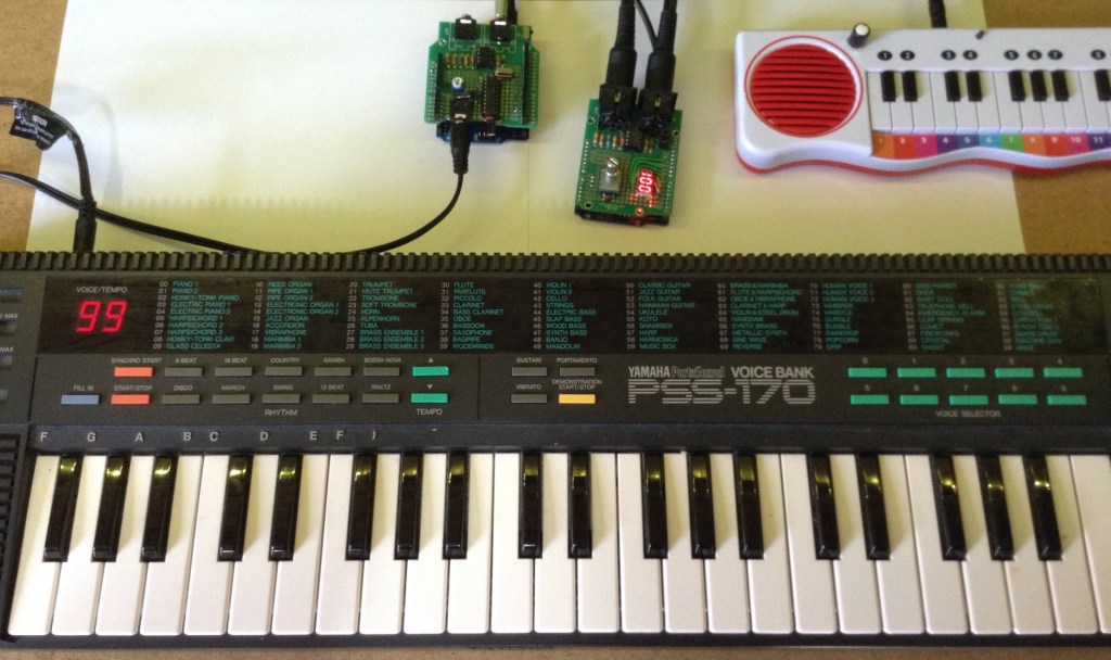
Having now made myself a Arduino OPL Bus Sniffer I’ve put it to some use grabbing the voice data from the YM2413 based Yamaha PSS-170 keyboard.
Warning! I strongly recommend using old or second hand equipment for your experiments. I am not responsible for any damage to expensive instruments!
These are the key Arduino tutorials for the main concepts used in this project:
- Majic Designs – Making Music with a Yamaha YM2413 Synthesizer
- Arduino OPL FM Synth
- Arduino OPL FM Synth – Part 2
If you are new to Arduino, see the Getting Started pages.
Parts list
- Arduino Uno.
- Yamaha PSS-170.
- Jumper wires.
The Circuit
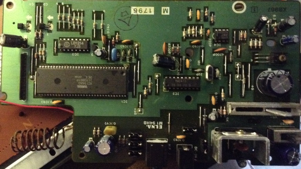
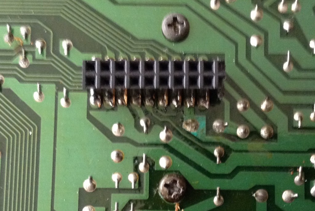
The plan is to use the Arduino to connect to the pins of the YM2413 in my Yamaha PSS-170 keyboard, which is the 18-pin chip footprint in the following photos.
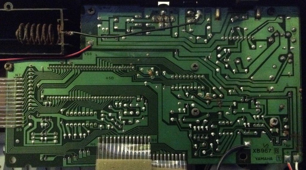
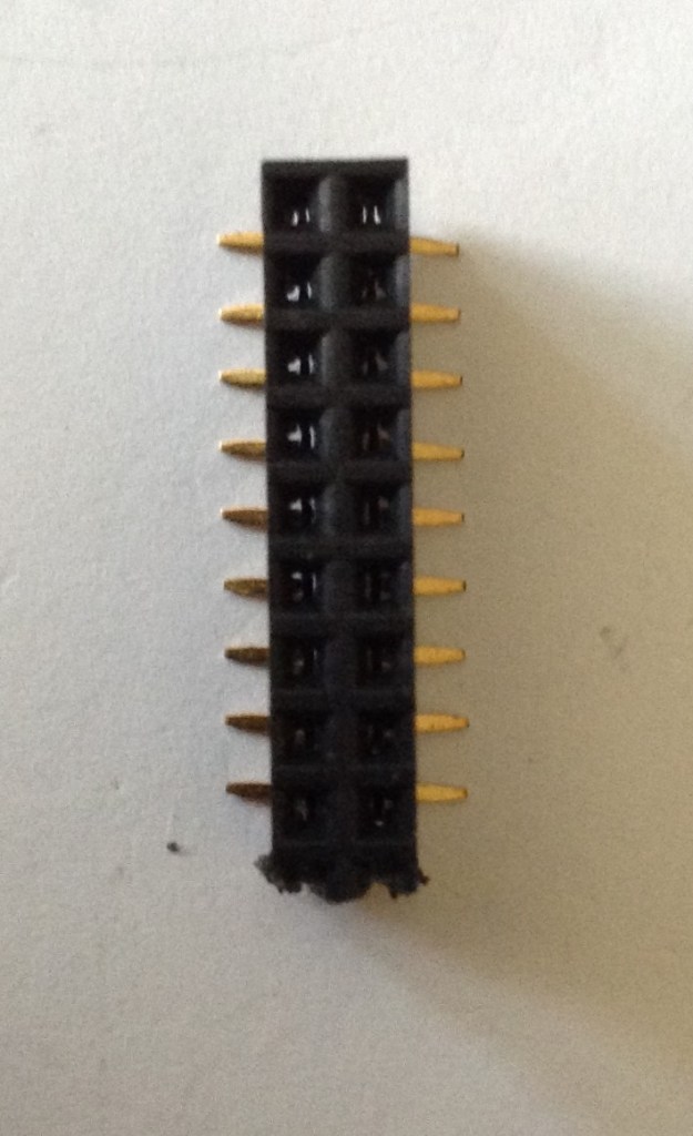
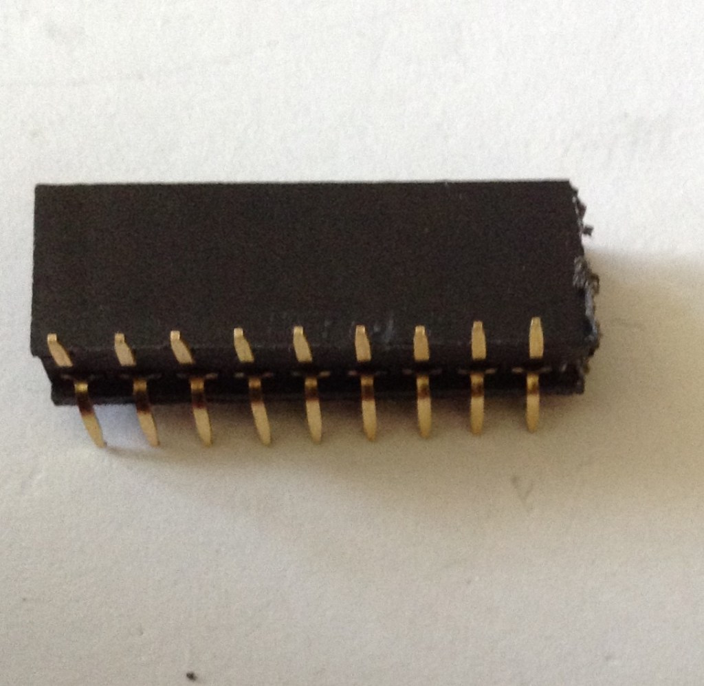
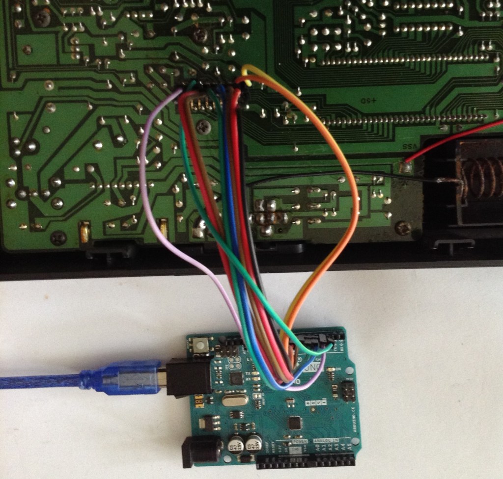
My first hope was to be able to use an IC socket or some spring-loaded pogo pins to connect to the chip, but I fairly quickly established that this wouldn’t really be feasible, so then I was faced with either unsoldering the chip and replacing it with a socket or soldering some connections on the back somehow. I opted for the latter, taking a cut-down DIL pin header and folding out the pins as shown below and soldering it to the rear of the PCB.
The PSS-170 is powered by a 9-12V supply but checking VCC on the YM2413 I can see that it is powered with 5V logic, so it is fine to hook up to the Arduino. To ensure signal integrity I hook the Arduino and YM24213 GND together.
Consequently, the following connections are required to hook up the sniffer application to a YM2413:
Arduino  YM2413    YM2413 Pin
   D2      /WE       11
OR         /CS       12
   D3      A0        10
   D4-D7   D4-D7     4-7
   D8-D11  D0-D3     17,18,2,3
   GND     GND       1
As mentioned last time, the writes are “triggered” by /CS and /WE being LOW. The code watches for one of these, using /WE throughout the code in the comments, but in the PSS-170 /WE is tied to GND so D2 needs to be connected to /CS in this case.
The Code
I’ve made a small adjustment to my Arduino OPL Bus Sniffer code. I get it to store any writes to registers 0 through 7 in an 8-byte array and when the 8th write occurs print them out in the following format:
{ 0x01, 0x81, 0x6A, 0x04, 0xFF, 0xF3, 0x01, 0x23 },
The original idea was to use this to watch for these voice changes and consequently end up with a whole series of these C code lines in the serial terminal, enabling easy cut-and-pasting into an Arduino sketch. Unfortunately it wasn’t quite that simple as the PSS-170 changes voice on every press of the 0-9 digit keys. This means that if the keyboard is on voice 00, to select 12 the voices cycle from 00 to 01 then 12 as the 1 and 2 keys are pressed. In order not to lose track of which voice number’s data I’ve just received I had to cut and paste them individually line by line…
To use the voices requires a very slightly modified version of my Arduino OPL FM Synth. The MD_YM2513 library has two functions that can be used to load in instruments. The voices used in my first application are loaded from the Arduino PROGMEM using loadInstrumentsOPL2() which converts the provided library of OPL2 voices into OPLL for use with the YM2413.
I have voices already in YM2413 format, so I use loadInstruments() directly. This doesn’t work with PROGMEM memory though, so I have to copy that out first.
This is the code I use to load a pss170 voice from my structure:
const uint8_t pss170[100][8] PROGMEM = {
   { 0x01, 0x81, 0x6A, 0x04, 0xFF, 0xF3, 0x01, 0x23 },
   ... and so on for 100 voices ...
};

void pss170LoadInstrument (byte instr) {
  uint8_t ins[8];

  if (instr >= 100) {
    return;
  }

  for (int i=0; i<8; i++) {
    ins[i] = pgm_read_byte(&pss170[instr][i]);
  }

  SYNTH.loadInstrument(ins);
}
The only slight quirk is that voices are listed as 00 to 99 on the front of the PSS-170, so program numbers 0 to 99 are used in Program Change messages to select the voices. But the MIDI spec states that instrument numbers that are presented to the user should be in the range 1 to 128. This means that any program change selection tool will be presenting 1 to 100 to the user to select one of the 0 to 99 voices.
I’m not sure of the IPR implications of pulling out Yamaha voices from one of their keyboards, so I’m not publishing the updates to my code for either the sniffer or the synth here, but the above hopefully gives enough information to reproduce this by anyone interested enough to do so.
Closing Thoughts
The video gives a comparison between my Arduino PSS-170 and my real keyboard. Curiously there are a few differences that can be noted:
- There is a slight tuning issue. The Arduino version sounds (to me) at little flat compared to the original. I guess that is something to do with the “F num” calculations happening in the code for the frequencies used.
- Some sounds include an effect on the real keyboard – either a vibrato or tremolo effect usually. These are not replicated on the Arduino version, so that might be something to think about in the future.
- Naturally the original keyboard includes a whole range of rhythms, auto-accompaniments, and alternative modes for chords and so on that aren’t implemented on the Arduino.
But in terms of the idea – of comparing voices from the original keyboard with one of these isolated chips – I’m really pleased with the results!
It would be really interesting to see if there is any merit in creating some kind of multi-chip instrument for fuller (detuned, etc) sounds… especially if they could be driven from the original keyboard! Imagine installing some additional chips in there somehow 🙂
Kevin

Nice work, congratulations! I was successful in importing the voices from Plogue CHIPSYNTH PORTAFM to the YM2413, as this application has a window with the parameter data of the voices in hexadecimal.
LikeLiked by 1 person
Hello. Nice work, congratulations. I am also working on a project with the YM2314.
LikeLiked by 1 person