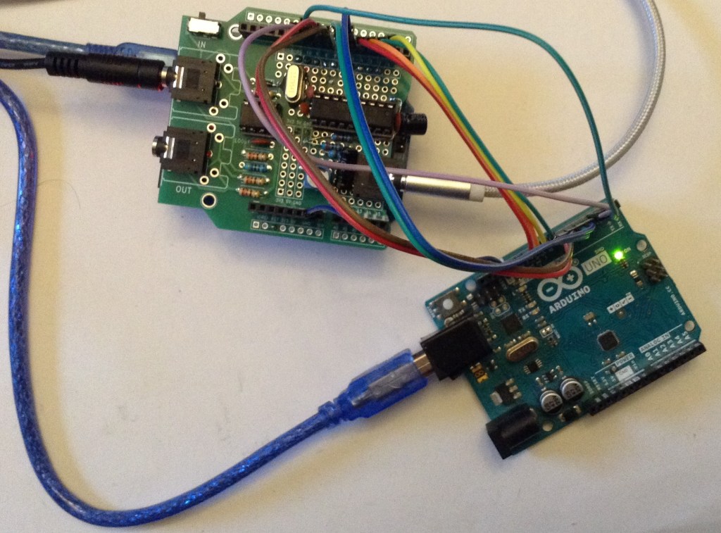
This is a slightly off-track application. I want to be able to probe a YM2413 chip “in situ” – i.e. installed in a keyboard, so I thought it might be interesting to develop an Arduino application that can monitor the data signals and pull out the data being sent to the chip.
Warning! I strongly recommend using old or second hand equipment for your experiments. I am not responsible for any damage to expensive instruments!
These are the key Arduino tutorials for the main concepts used in this project:
- Majic Designs – Making Music with a Yamaha YM2413 Synthesizer
- Arduino OPL FM Synth
- Arduino OPL FM Synth – Part 2
If you are new to Arduino, see the Getting Started pages.
Parts list
- Arduino Uno.
- YM2413 device to monitor.
- Jumper wires.
The Circuit
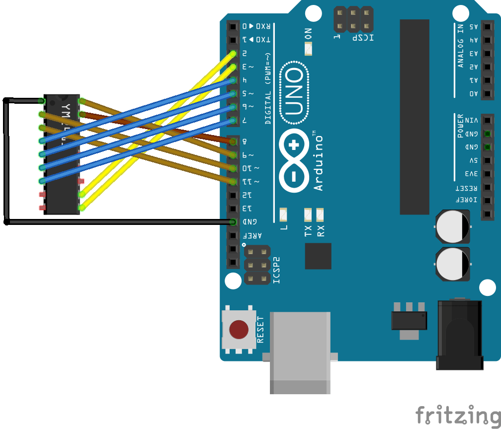
The above shows the connections required to hook up the sniffer application to a YM2413. The links required are as follows:
Arduino  YM2413    YM2413 Pin
   D2      /WE       11
   D3      A0        10
   D4-D7   D4-D7     4-7
   D8-D11  D0-D3     17,18,2,3
The idea is to be able to use direct PORT IO to access the registers, so a simple mapping is required. However, the results will be sent back over the serial port (USB) so D0/D1 can’t be used. Also I’m going to use an external interrupt to trigger the value reading, so that means the triggering signal (in this case /WE) has to be on one of D2 or D3. In the end I settled for wiring it up in two halves with YM D0-D3 mapped onto PORTB (Arduino D8-D11) and YM D4-D7 mapped onto PORTD (Arduino D4-D7).
Update: After examining the actual board I want to monitor and re-reading the datasheet it would appear that either /CS or /WE might be used to trigger a write, so although the code talks about /WE throughout it might be necessary to hook that jumper wire up to /CS instead depending on the situation.
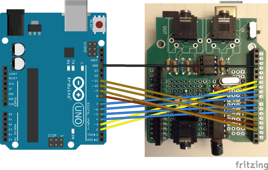
Here are the connections for my Arduino OPL FM Synth – Part 2.
The Code
The protocol used by the YM2413 is very well described here: https://arduinoplusplus.wordpress.com/2020/02/22/making-music-with-a-yamaha-ym2413-synthesizer-part-2/
The key feature that I’m exploiting is that the data and address bits are setup and then /WE is set LOW to activate the action. Consequently I can monitor all data, address and /WE lines and then when /WE goes LOW take a reading.
Typically the address will be set first followed by a data action although it is possible to write more data to the same address without having to specify the address again.
In order to capture the data at the right moment, I’m using the external interrupt feature of the Arduino. Basically it is possible to get the Arduino to stop everything it is doing and run some kind based on the state of one of its IO pins. I’ve configured D2 to generate an interrupt on a FALLING edge – i.e. when it goes from HIGH to LOW. Then I’ve hooked up D2 to /WE.
This means there are two threads of activity in this code:
- The main loop monitors a buffer of readings and if there are new readings it will print them out to the serial port.
- In parallel, whenever /WE triggers the external interrupt via D2, the data is read and stored in the same buffer for printing out later.
This approach means that the data is read as quickly as possible in response to writes to the YM2413, but in slower time the data can be printed out to the console. This takes advantage of the fact that the writing to the YM2413 will occur in bursts of activity with gaps between them.
The interrupt is enabled with the following:
attachInterrupt(digitalPinToInterrupt(WE_PIN), ymSampler, FALLING);
The buffer that stores the values is a “circular buffer” of 256 values, which means that if I used an unsigned 8-bit variables as the index I can simply do idx++ and it will automatically wrap-around from counting 255 back to 0.
Two indexes are required, a “write pointer” which details the next space in the buffer to use when a new value comes in; and a “read pointer” which details the last unread piece of data in the buffer.
If the two pointers are carefully managed, then it is possible to check if there is new data to be printed out simply by seeing if the write and read pointers are different. Here is the main code:
uint8_t addr;
void ymSampler() {
  uint8_t pB = PINB;
  uint8_t pD = PIND;
  uint8_t rD07 = (pD & 0xF0) | (pB & 0x0F);
  uint8_t rA0 = (pD & 0x08);  // D3

  if (rA0 != 0) {
    ym_addr[widx] = addr;
    ym_data[widx] = rD07;
    widx++; // auto wrap around
  } else {
    addr = rD07;
  }
}

void loop () {
  while (widx != ridx) {
    uint8_t adr = ym_addr[ridx];
    uint8_t dat = ym_data[ridx];
    // print out adr and dat...
    ridx++; // auto wrap around
  }
}
ymSampler is the interrupt routine and will read in all the IO values using Arduino direct IO from PORTB and PORTD at the top, then combine the top 4-bits of PORTD with the bottom 4-bits of PORTB to get the full D0-D7 value.
It will check the address bit and if it is an address write then the data is stored in the address variable for use when the next data write happens. When that happens the data is stored in ym_addr[] and ym_data[] at the current write pointer widx.
The main loop monitors ridx and widx and if different will keep reading (and printing out) the unread items in the buffer.
Results In Use
Here is the output from my Arduino OPL FM Synth – Part 2 starting up:
1	0	0xF = 0x0
3	1	0xE = 0x0
5	2	0x30 = 0x30
7	3	0x31 = 0x30
10	4	0x32 = 0x30
37	5	0x33 = 0x30
37	6	0x34 = 0x30
37	7	0x35 = 0x30
37	8	0x36 = 0x30
37	9	0x37 = 0x30
37	10	0x38 = 0x30
37	11	0x30 = 0x30
37	12	0x30 = 0x0
37	13	0x31 = 0x30
37	14	0x31 = 0x0
37	15	0x32 = 0x30
37	16	0x32 = 0x0
37	17	0x33 = 0x30
37	18	0x33 = 0x0
37	19	0x34 = 0x30
37	20	0x34 = 0x0
37	21	0x35 = 0x30
37	22	0x35 = 0x0
37	23	0x36 = 0x30
37	24	0x36 = 0x0
37	25	0x37 = 0x30
37	26	0x37 = 0x0
37	27	0x38 = 0x30
37	28	0x38 = 0x0
37	29	0x0 = 0x33
37	30	0x1 = 0x31
37	31	0x2 = 0x5A
37	32	0x3 = 0x17
37	33	0x4 = 0xB2
37	34	0x5 = 0xB1
37	35	0x6 = 0x50
37	36	0x7 = 0xF5
The first two columns show how the write and read pointers change. Note how the write pointer quickly reaches 37 whilst the read pointer catches up in slower time.
In terms of what is going on:
- The writes to 0xF and 0xE are initialising the TEST and rhythm control registers to 0.
- The writes to 0x30-0x38 initialise all 9 channels to the default voice. In the MD library this is voice 3 (piano) which involves writing 3 to the top 4-bits of the appropriate register, hence the write of 0x30. The lower 4-bits represent the volume (see below).
- The following pairs of writes represent a setting of the volume to full, whilst preserving the current voice (hence writing 0x30 again) followed by setting the voice for the channel to 0, the custom voice (hence followed by a write of 0x00). This happens for each channel 1-9 (0x30 to 0x38).
- The final set of writes to addresses 0x0 to 0x7 is the library loading the custom voice data for the first voice.
There was one oddity. Throughout the code the maximum volume is given as 15 (0xF) and the datasheets talks about volume as a 4-bit entry in a register. But it turns out (from reading the library code) that the volume is actually set as an attenuation value. So the maximum volume is obtained by writing a 0 into the 4-bit volume register and the minimum volume (i.e. maximum attenuation) is obtained by writing 15 (0xF).
Closing Thoughts
This works surprisingly well. It is especially pretty responsive running off interrupts and the circular buffer between interrupt routing and main loop means data is captured and printed out quite nicely.
I could now start to include a decode routine to expand out the data values into the register components with additional text to make it completely stand-alone, but actually this is probably all I really need for the moment.
Kevin
