A little while after my last set of experiments for a Arduino MIDI Telephone Ringer I found a video from “Gadget Reboot” showing how to use the KS0835F subscriber line module from an Arduino to interface to a phone more easily. So I bought some and this is the start of a set of new experiments looking at the potential uses of this module with MIDI. In this first part, I’ve built an interface board and have managed to get the phone ringing!
Warning! I strongly recommend using old or second hand equipment for your experiments. I am not responsible for any damage to expensive instruments!
These are the key Arduino tutorials for the main concepts used in this project:
If you are new to Arduino, see the Getting Started pages.
Parts list

- Arduino Uno
- KS0835F SLIC module (e.g. from Aliexpress)
- Analogue telephone
- MIDI interface
- KS0835F Interface Circuit from https://github.com/GadgetReboot/KS0835F_Phone_SLIC
- 3x 100nF capacitor
- 1x 10uF capacitor
- 4x diode rectifier 1N4004 (D0-41)
- 1x diode 1N4148
- 1x diode TVS P6KE82 (D0-41) – see note below
- 1x resistor 1MΩ
- Headers as required
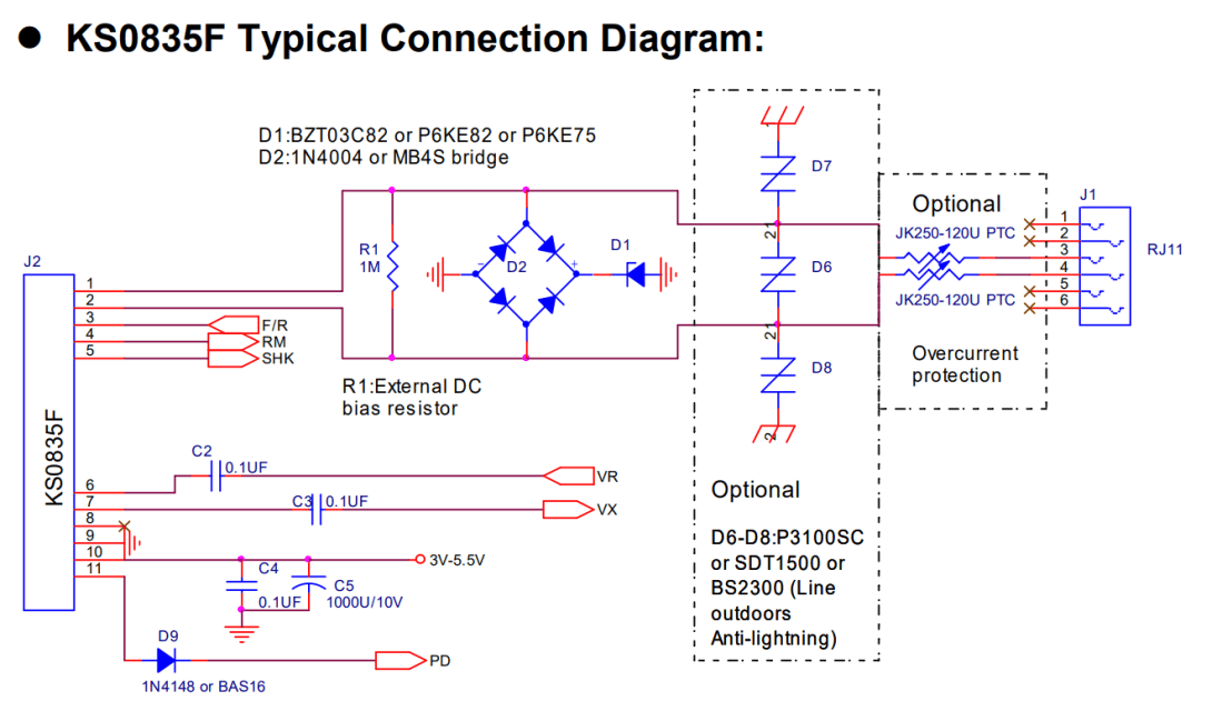
I struggled to find a TVS P6KE82 diode, but from comparing specs and descriptions ended up getting a BZT03C82-TR 82V Zener Diode (600W). This seemed the closest from the available range to the required diode (based on the discussion from the video as to what the diode was doing) and the KS0835F datasheet has the following alternatives listed:
- D1: BZT03C82 or P8KE82 or P6KE75
- D1: 1N4004 or MB4S bridge
The Circuit

This is my Fritzing diagram for my protoboard version of the circuit described in https://github.com/GadgetReboot/KS0835F_Phone_SLIC which itself is pretty much an implementation of the circuit from the KS0835F datasheet (reproduced below):
The pinout for the Arduino is via the 10-way header as follows:
- GND
- 5V
- Audio OUT
- Audio GND
- Audio IN
- Audio GND
- SHK: On hook detection
- RM: Ring mode
- F/R: Forward/reverse
The basic principle to make the phone ring is to set RM=HIGH and then toggle FR at the required 20Hz ringing signal frequency. Once complete, set RM=LOW. For the ringing to work properly however, it should only be sent when the handset is on hook, so SHK can be used to check that if required.
A note on Power Consumption
The KS0835F datasheet shows the following:

The Arduino can (apparently) realistically source up to 500mA from its 5V pin, which is also the limit that USB power should be able to deliver, so we should be fine for driving a single module this way even when off-hook or ringing. If we want the Arduino to drive several modules then a separate power supply will be required.
Here is my protoboard version.
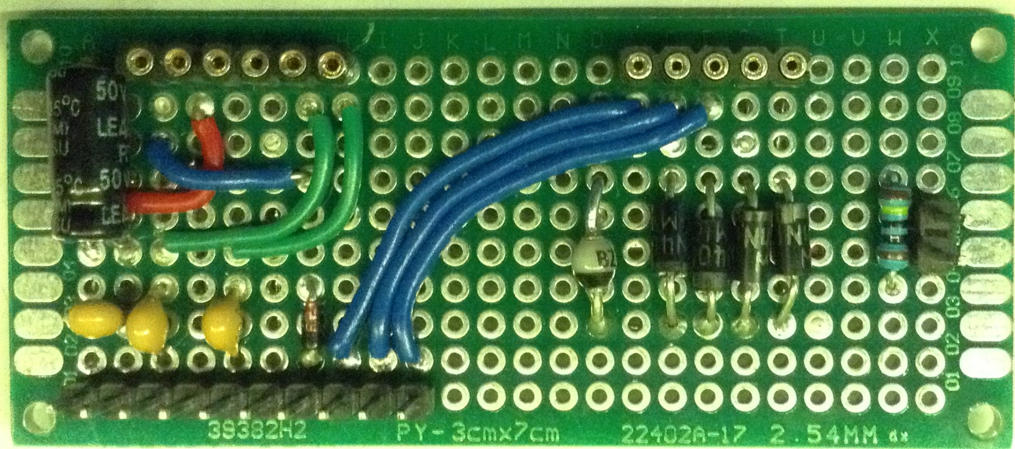

I was hoping to use pin header sockets for the SLIC as I don’t quite yet want to be soldering it down! But unfortunately the right-angled pins on the SLIC aren’t very long, so it wouldn’t work with normal headers. So I opted for the “round socket” style header socket in the hope I could make the SLIC fit. It doesn’t.
So in the end I had a weird collection of jumper wires, via solderless breadboard, and a little bluetack to hold the headers in place on the SLIC!

It wasn’t what I was anticipating, but it worked ok enough for this first experiment!
Arduino Pin Connections:
- RM <-> D2 (OUTPUT)
- F/R <-> D3 (OUTPUT)
- 5V
- GND
A MIDI interface is also required to link into RX. In the photo I’m using my new Arduino Stackable TRS MIDI Interface as it is so convenient but any of the Arduino MIDI Interfaces or Ready-Made MIDI Modules would be fine.
The Code
To get the phone to ring requires the following:
Set RM HIGH
Toggle F/R at a 20Hz rate between HIGH and LOW for as long as required
Set RM LOW
I’ve adjusted the code from the original Arduino MIDI Telephone Ringer.
You can find it on GitHub here.
Closing Thoughts
This module is a lot more convenient than messing around with H-Bridges and transformers and the like and it has the added bonus of being able to provide audio and should work with a much wider range of phones. I just need to decide how best to connect to it via those short pins.
And a massive thank you to GadgetReboot for doing all the hard work in the first place of working out how best to use it.
Watch this space for more.
Kevin

Hi Kevin,
Any idea what the purpose is of the Diode Bridge on the output side? I was having trouble and just removed it and am running my phone straight of the output and it works great.
LikeLike
I’m not an electronics person really, but the video I was referring to describes it as “voltage clamping” so I figured it was some kind of output protection to stop it generating too high voltages when in use. See https://youtu.be/N3Z2zw0gRz8?si=IGnMXXNZYPWvxysl&t=104
Kevin
LikeLike