Here is the build guide for my 3V3 MIDI Module PCB.

Warning! I strongly recommend using old or second hand equipment for your experiments. I am not responsible for any damage to expensive instruments!
These are the key tutorials for the main concepts used in this project:
- PCB Design in KiCad from Arduino Uno Dual Merge MIDI “Shield” – Part 2.
- Ordering your PCB: a Beginners Guide for Manufacturer Options
If you are new to microcontrollers, see the Getting Started pages.
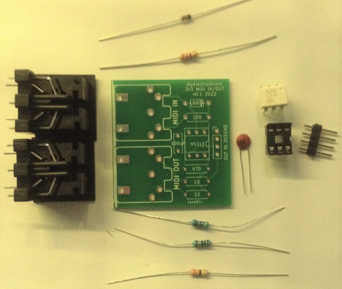
Bill of Materials
- Naturally, you’ll need a 3V3 MIDI Module PCB (GitHub link below).
- Resistors: one each of 220Ω, 470Ω, 10Ω, 33Ω.
- 100nF ceramic capacitor (not 100uF as labelled on the board!).
- 1N914 or 1N4148 diode or similar.
- H11L1 optoisolator.
- 2x 5-pin 180 DIN sockets (see photos for footprint).
- Optional: 6 pin DIP socket.
- 4-way header pins.
The socket is optional but recommended.
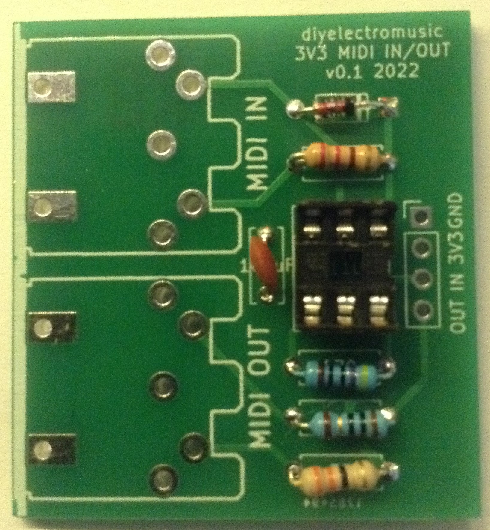
Build Steps
The build should be a relatively straightforward through-hole components build. All components should be placed on the same side of the board, as indicated by the markings.
I recommend the following order:
- Diode and resistors
- 6-way DIP socket (if used).
- Capacitor
- 4 pin header.
- H11L1 if soldered directly.
- 5-way DIN sockets.
Here are some of the build steps in photos.

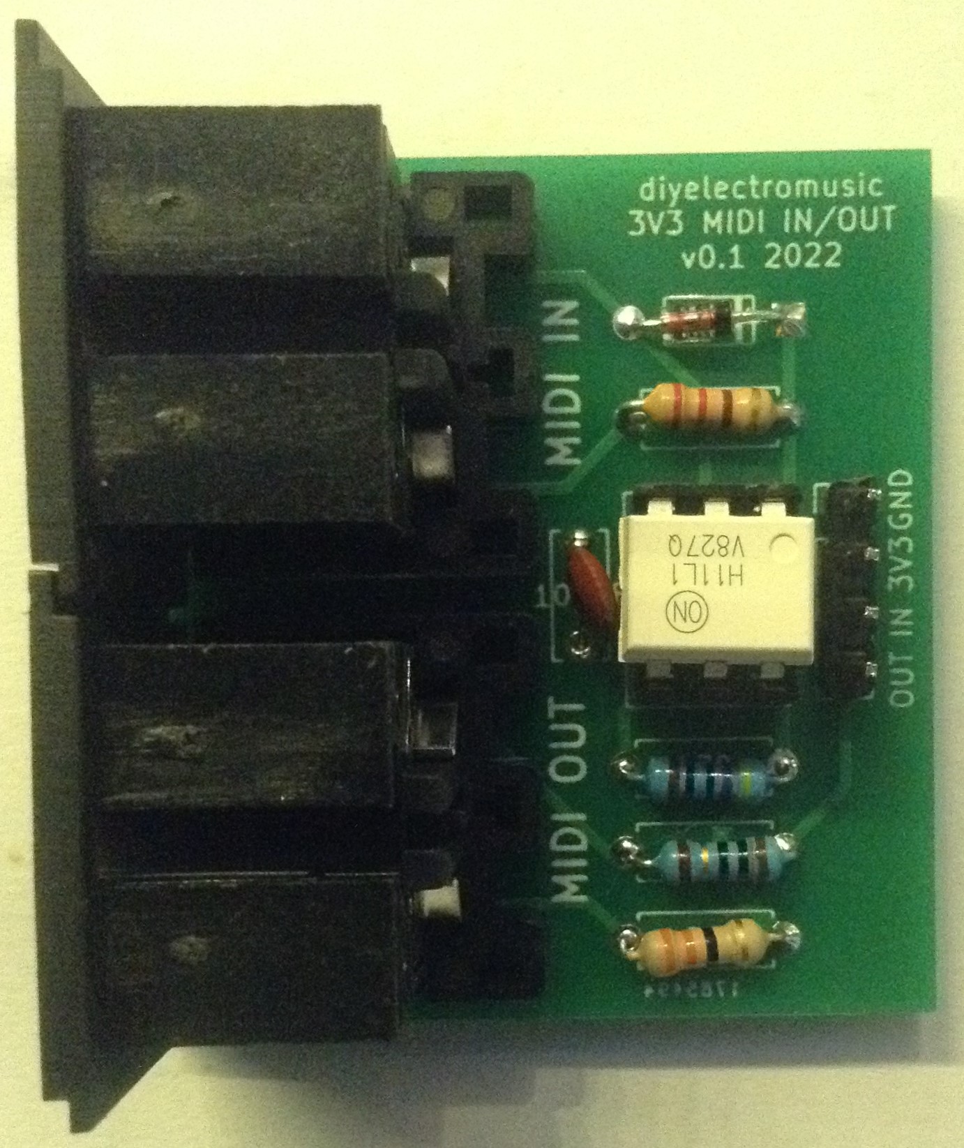
To use, the following connections are required:
- 3V3 power.
- GND.
- IN connected to a 3V3 microcontroller’s RX.
- OUT connected to a 3V3 microcontroller’s TX.
In the photo at the top of this post, you can see this connected to a Raspberry Pi Pico.
Testing
I recommend performing the general tests described here: PCBs.
PCB Errata
As mentioned above there is an error in the labelling of the capacitor. It should be 100nF not 100uF.
As I mentioned before, I do NOT recommend using this board with more expensive single board computers such as the Raspberry Pi. It is designed for simple connections to microcontrollers. It will probably work fine, when everything else in the circuit is working fine, but if something goes wrong (e.g. you plug in a faulty MIDI lead or device) there is no protection for the pins driving the output circuit and you risk damaging your expensive (and hard to source these days) Raspberry Pi or similar board!
Potential Future Enhancements:
- A future version could include some mounting holes (I did think about it, but then decided not to).
- An output buffer for additional protection.
- A MIDI activity LED might be useful in the future.
You can find the PCB design files on GitHub here: https://github.com/diyelectromusic/sdemp_pcbs/tree/main/MIDIModule3V3
Closing Thoughts
Once again, I used the Seeed Fusion pcb service, spending some of my discount vouchers and I’m very happy to keep doing so. As far as I’m concerned the boards so far have always come back in good time and have been perfect for what I need.
Also, as always I have a couple of unpopulated pcbs spare if anyone is interested in having one. Just ping me a message via some suitable route. Alternatively, all the required design files are on GitHub.
Kevin

In your schematic you show a 100uF capacitor, but in your build list you used a 100nF 104 disc capacitor. Which is it supposed to be?
LikeLike
Thanks for the comment – well spotted! Yes, that should be a 100nF not 100uF capacitor. I’ve added some notes accordingly.
LikeLike
Thanks for the quick response, I thought so, but I just wanted to make sure. Your blog posts have been incredibly helpful for the midi circuits I’ve been tinkering with for the Pi Pico and Daisy Seed!
LikeLike
Great! That’s nice to hear 🙂 Do feel free to share what you’re up to if you wish!
LikeLike
Hi Kevin,
Sure thing! The first embedded project I did was this one:
LikeLike
Hi Kevin,
The post was a while ago, but would you still have any of the unpopulated PCBs for this 3v3 MIDI project? I would be interested in one as it will save me getting 5 made and having 4 spares :-). I want to interface for an ESP32 to port my MIDIFile library (https://github.com/MajicDesigns/MD_MIDIFile) to use LittleFS instead of the external SD card.
I am located in Australia.
Marco
LikeLike
Yes sure! Ping me an email diyelectromusic at gmail with your details and I’ll pop something in the post. Anything else of interest while I’m sending stuff? I don’t know what ESP32 you’re using but I have some XIAO PCBs with MIDI and prototyping areas that should be usable for the XIAO/QTPy style ESP32 boards if that is any use too…
As I said in my posts, this is a pretty simplistic MIDI implementation. MIDI IN should be fine, but MIDI OUT is unbuffered so there is no protection from overload of the MCU’s IO pins if there is a problem with whatever you plug in 🙂
Kevin
LikeLike