One year ago I posted the following two articles:
Shortly followed by an associated video on YouTube and so the Simple DIY Electronic Music Projects blog was born! They were then followed by the Arduino MIDI Tone Module and many others since.
So in honour of my one-year anniversary, after more than 180 posts, including the launch of the Lo-Fi Orchestra, I wanted to return to those “tone” roots and do something slightly different.
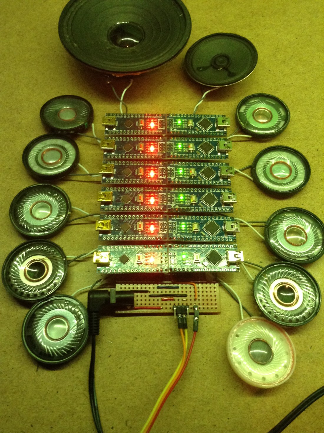
Here are twelve Arduino Nanos, each with a speaker and armed with nothing more than the MIDI library and the tone() function bringing you my favourite selection of music from the whole of the Star Wars saga – the fanfare from the last scenes of Star Wars Episode IV A New Hope.
Watch it in full below.
Warning! I strongly recommend using old or second hand equipment for your experiments. I am not responsible for any damage to expensive instruments!
These are the key Arduino tutorials for the main concepts used in this project:
If you are new to Arduino, see the Getting Started pages.
Parts list
- 12x Arduino Nano
- 12x 8 ohm or old headphone speakers
- 12x 220Ω resistors
- MIDI IN – for example an Arduino MIDI Interfaces or one of the Ready-Made MIDI Modules.
- Either stripboard or breadboard and jumper wires
The Circuit

The circuit is largely just a “helper” board to make it easy to power 12 Arduino Nanos, allow them to share the same MIDI in signal, and have them all connected to their own speaker.
Things to note about this build:
- Only four pins of the Arduino Nano are connected:
- VIN
- GND
- RX for the MIDI in signal
- D2 for the audio output
- This is using VIN to simplify the track layout on the board. You could use 5V if you wished, but that is on the same “track” as one of the GND pins, and the other GND pin is on the same “track” as RX. By using VIN, GND and RX it is possible to have all three tracks span the whole board unbroken.
- Using VIN means it requires a power supply of 6-12V. You can’t put 5V in VIN and have it work (reliably).
- The MIDI interface requires 5V power (usually), so one of the Arduino Nanos does have its 5V connected – but it is use as a “5V out” for the MIDI module. This means in that one place, the GND track needs cutting and “routing around” the 5V pin.
- Ideally you’d be using 12 speakers that are all very similar. I had two a bit quieter than the rest and one too loud. The louder one was relatively easy to sort out – I added an extra resistor – but I couldn’t really do anything about the two quieter ones as I didn’t want to limit any of the others.
The Code
The idea is to create 12 of the Arduino MIDI Tone Modules, with each one on a different MIDI channel, and play them like a single 12-note polyphonic tone module.
Note it should be noted that there are many other ways to achieve this, in fact as part of the 180+ projects posted during this last year, I could have looked at:
- Arduino Multi MIDI Tone Module – a similar project to this one, essentially stacking up four of the Arduino MIDI Tone Modules with a common MIDI In.
- Arduino MIDI Multi-Tone Module – a project showing how a single Arduino can be made to make up to three tones itself.
- Arduino Tone Polyphony – the first in a series of posts showing how to get even more tone() like notes from a single Arduino. At the end of the series, I managed full 12-note polyphony (with a few limitations!)
Not to mention a whole host of synthesis approaches and alternative microcontrollers. But the idea was to return to those first two projects and do something with those.
Consequently the code used here is almost completely unchanged from the Arduino MIDI Tone Module code. The only changes are minor:
- The output pin is D2 to make using the stripboard easier.
- The MIDI channel is changed for each board. Note that I’ve not used channel 10 as this is typically used for a drum track, so I’m using MIDI channels 1-9 and 11-13.
- I added a “note on indicator” in the shape of LED_BUILTIN. This gets turned on when a noteOn is received and turned off when noteOff is received. This was useful to let me know when things are happening on which boards!
The Music
As with all my Lo-Fi Orchestra performances the music score is programmed in by me using MuseScore3. There are twelve parts, each set to a different MIDI channel (1-9,11-13) with a loose “six part high, six part low” kind of structure. The score is part my own listening, part extracts from different MIDI files (which unfortunately don’t tend to come with attribution or credits!), where appropriate, and part glue by me to join it together.
Once complete, the score is changed to remove all expression(!), saved as a MIDI file and then tweaked using MidiEditor to remove any Program Change messages from the start, which tend to overload the MIDI handling when all sent at once!
It is “conducted” from an old laptop using MidiBar – which is part of MidiOx via my Roland UM-ONE MK2 MIDI interface.
Closing Thoughts
The blog has come a long way this last year. I certainly never anticipated the creation of the Lo-Fi Orchestra. But even after some 180 posts, my ideas list is still pretty long, so there is still plenty more to do if I feel so inclined.
If you like what you see do pop over and follow me on social media. You can find me on:
- Twitter as @diyelectromusic
- Facebook with a diyelectromusic page and a Lo-Fi Orchestra page
- my YouTube channel
And I have accounts on Github, Hackaday.io, Electromaker.io and if all else fails you can buy me a Ko-Fi if you are so inclined.
Kevin

I am working on a music puzzle, and I want to create a puzzle that requires physical manipulation to produce the correct song. So, something like your device here that has 12 controllers , each producing a tone, but if placed in the wrong order would produce incorrect melody. Eg: the tone for note of A is coded to arduino 1,and note B frequency to arduino 2. If you connect 2 into the ‘slot’ for 1, then note B would play when wanting an A. Any suggestions on how to take your project and make the arduino modular while retaining the frequency they would play?
LikeLike
Jessica, that sounds like fun!
In terms of approaches to this kind of thing, if I understand you correctly, it sounds like you are trying to build something that is very similar to a physical step sequencer. This is something I’ve wondered about doing myself a number of times now, but haven’t looked into it in detail.
My approach to this would be to split the problem up into the following:
* The music generation part – any of the step sequencer projects on my website could act as a starting point for this.
* The “reading” and encoding of the steps part – I have a few ideas of how this might happen.
* The mechanical design of the physical elements – this is not an area I know much about!
Do you already have a mechanical/switching/encoding design worked out? I’m guessing from your question perhaps not, so I’m answering on that basis – so apologies if that is assuming too much! If you just wanted a comment on the music part let me know with a bit more context on what you already have, and I’ll have another go!
In terms of the first part, as I say, looking over any of my existing step sequencer projects would get quite a way into this I think. I want to detect which note to play at each point in the sequence, assuming they are deliberately set up by the musician. In your case the note is determined by the choice of the person attempting the puzzle.
The last part I’m not sure I can help with, but in terms of actually working out what “notes” each step has to play (the middle part) I have a few ideas on how to use physical locality as an indicator.
I’ve wondered about both centralised processing and distributed processing approaches. I believe you are suggested a distributed approach, where each step is its own processor and possibly its own note-producing system. The pros of such an approach I think are around the possibility of a much slicker interaction if the mechanical design supports it. But I think there are a number of downsides to going this way:
* It will be expensive in terms of number of microcontrollers required and their power usage. For full autonomy, each will need its own independent power.
* Miniaturisation might be a challenge too – although something like the Adafruit Flora or Gemma might do it (but at £8 a note will add up!)
* I don’t believe it will be easy to work out relative physical proximity on the scale of a table-top puzzle. I’ve had a few ideas in this area: using wireless comms, Intrared LEDs/sensors, localised light detection, even magnetic contacts, but I’ve not felt anything was particularly robust enough to try so far.
* It will be complex in terms of scheduling and sequencing – how will each device know when to play it’s note?
* It might end up quite complex to configure and programme – each device will need to be told what note to play.
Taking a centralised approach I think might be a simpler way forward. By this I mean having one microcontroller or single board computer that uses its IO to scan a number of sensors (one for each step) and determine which physical thing is in which location and therefore which note to play. Some ideas I’ve had for a physical step sequencer like this include:
* Digital IO – using a bus/matrix arrangement from a microcontrollers IO pins, similar to how a keyboard matrix is decoded. Using, say 4 pins, would allow the digital encoding of up to 16 “notes” for any physical step. The MCU could “scan” each location to see what combinations of the four pins are active and thus decode the note in that position.
* Analog IO – similar to the above, but instead of 4 pins encoding a number to be read, the system uses analog inputs to detect a voltage at each step. Different levels of voltage correspond to different notes to be played.
* Some kind of “bus” arrangement – where each step is linked to the next and the order determines the sequence somehow (similar to how programmable LEDs are programmed – data is “shifted” through them).
* Image recognition – using a camera and more processing power, the “play area” is scanned and some advanced object recognition is used to work out which pieces (e.g. coloured bricks or similar) are in which order and plays a sequence accordingly.
In terms of implementation details for the above, the ideas I’ve had for digital IO include:
* “edge connector” slots – modules are slotted into a “backbone” with a “keyed” set of connectors.
* jumper header pins – modules are mated with a set of header pins with “keyed” connections.
* magnetic contacts – as above but using magnetic/spring/other contacts instead of edges/pins.
* arrays of switches – switches get activated by the physical design of plugged-in modules.
The mechanical design for any of these will be really important, especially for things to be plugged in and out quite a lot!
Ideas for analog still need a connection, but maybe just two, but the keying happens by having different resistance across the two terminals, thus changing the voltage sensed for that location.
Ideas for physical linking at present include data in/out shift approaches, similar to how WS2812 programmable LEDs work; use of existing microcontroller buses – e.g. I2C devices with individual addresses; or even something like the “little bits” kits with magnetic contacts.
I don’t have much experience of image recognition, but have seen a number of projects around the web doing this kind of thing, so I guess it could be possible!
Does any of that sound useful? That is what springs to mind.
As I say, get back to me if I’ve missed your point in this! And either way do let me know how you get on and what your next steps are.
Good luck!
Kevin
LikeLike
Thhanks for the post
LikeLike