Having now done both MIDI In and MIDI Out for the Raspberry Pi Pico, and having seen the Adafruit MIDI Feather Wing and the design for “packs” (“shields” in Arduino speak or “wings” in Adafruit Feather speak) from Pimoroni, I wanted a convenient equivalent for my MIDI In and Out and this is the result.
Warning! I strongly recommend using old or second hand equipment for your experiments. I am not responsible for any damage to expensive instruments!
These are the key tutorials for the main concepts used in this project:
If you are new to microcontrollers, see the Getting Started pages.
Parts list
- 20×8 proto board
- 2x 5-pin PSB mounted DIN sockets
- 2x female 20-way header sockets (ideally, “shallow” version – mine are “5mm plastic height” versions)
- 2x jumpers
- H11L2 optoisolator
- 1x 220Ω resistor
- 1x 10Ω resistor
- 1x 33Ω resistor
- 1x 1N914 diode
- 2x 3-way male header pins (or 2×3 block of male header pins)
- Jumper wires
The Circuit
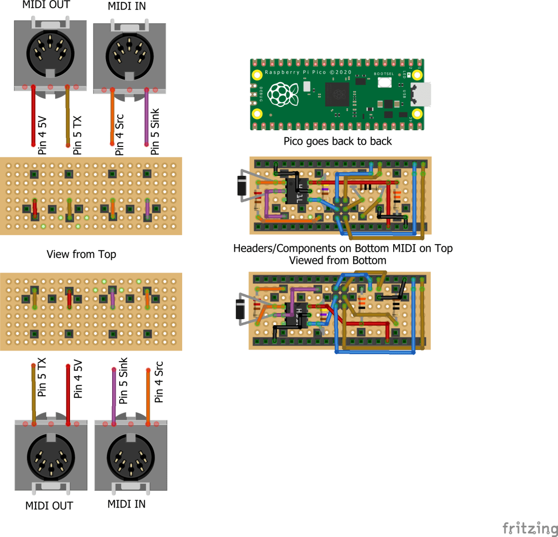
This is essentially the combination of the two MIDI circuits described in my previous projects. There is one slight change on the MIDI in side – I’ve swapped the 6N138 optoisolator for a H11L2 for two reasons: it is only 6 pins, not 8, which makes it easier to fit in, and it has one less resistor required compared to the 6N138. I wish I could take credit for this choice of component, but actually I followed the design of the Adafruit MIDI Feather Wing, so I already know it works well with 3.3V systems.
There are two variants of the circuit shown. The top one is a “right hand” version, i.e. the MIDI sockets face to the right when the Pico’s USB connector is at the top. The bottom one is a “left hand” version, so the MIDI sockets face to the left. In both cases I’ve shown both a “top view” looking down on the MIDI sockets, and a “bottom view” looking up from the Raspberry Pi Pico side at the components and headers.
I’ve only built and verified the bottom one – the “left-handed” version – as that will sit nicely in my Pimoroni “dual expander” alongside my Pico Audio (which I still haven’t played with!). I believe the top one should also work and it looks right, but I haven’t verified that I’ve got it right.
It should also be noted that this is the simplest design that could possibly work. It doesn’t include any buffering on the MIDI out and there is no MIDI thru implementation or indicators of MIDI activity. But it works nicely for me.
When designing this circuit I had the following in mind:
- It had to be both MIDI In and Out.
- It had to fit within the footprint of the Pico.
- Ideally it would allow me to choose between UART 0 and UART 1 somehow.
- Ideally it would be just one board with the components on one side and the MIDI sockets on the other.
- It would follow the design of the Pimoroni “packs” in style.
- It would be compatible with the Pimoroni expanders.
- It could also be used directly with just a Pico.
I think I’ve managed all of these. Here are the build steps. The first thing is to cut down and prepare the proto board. The footprint of the Pico (and the Pimoroni “packs”) is 8×20. I was originally going to use a “pico proto” but these are designed to link the Pico’s header pins to the proto area… but then that doesn’t leave enough space for the MIDI sockets, so I went back to standard proto board.
The MIDI sockets have pins that are slightly too large for the PCB holes, so they need drilling out. This has the disadvantage that the holes don’t have any remaining conducting material to solder on to! We can get around this, but it does mean that the MIDI sockets aren’t as structurally strong as they could be.

As I’m attempting to get all the components on one side only, and as the MIDI sockets fit quite flush to the board, it isn’t possible to solder “through hole” style. Instead I opted to solder “dead bug” style – i.e. solder on the component side for the most part – even the optoisolator…
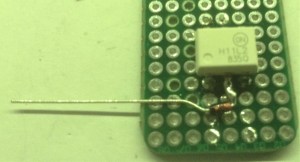
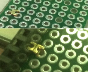
One of the consequences of doing things this way is that I don’t want to the legs of the optoisolator to poke through the board, so the first thing to do was to trim them down as follows.


Ordinarily I’d try to solder something like an optoisolator last, or even use a socket, to avoid the possibility of heat damage. But in this case I need the legs to solder other components on to, so this had to go on first. I was just really careful to use the absolute minimum heating necessary to do what I needed.
The first passive components to go on where the diode and resistor for the “in” circuit as these need to link across the pins of the optoisolator.
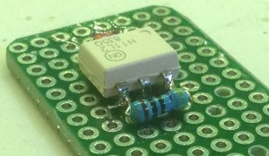
At this point I needed the MIDI sockets so I can start soldering things to them, so the “in” socket went on next followed by the second “in” resistor and the linking wires and ground for the optoisolator.


Next was the “out” socket and the 2×3 male header pins for the UART selector jumpers.

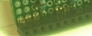
One thing I had to chew over was how to connect to the 20-way female header pins, as I’d be wanting to solder to them on the opposite side to their own fixings. The solution I came up with was to use some of the “inserts” from a female header pin – you can pull them out with some pliers – trimmed and bent and inserted into the PCB holes for the female headers before soldering on the headers.

Having these inserted for 5V and GND on one side then allows me to add the 5V and GND links to the sockets and optoisolator. Then the five connections on the other side for the two UARTs and GND allow me to get the female headers soldered on too.

Next are the RX and TX links between the MIDI sockets (via the optoisolator in the case of the “in” side) and the UART selector jumper.

Finally the GND for the MIDI out can be connected followed by the four UART connections to the UART selection jumper (UART 0 RX and TX, UART 1 RX and TX).

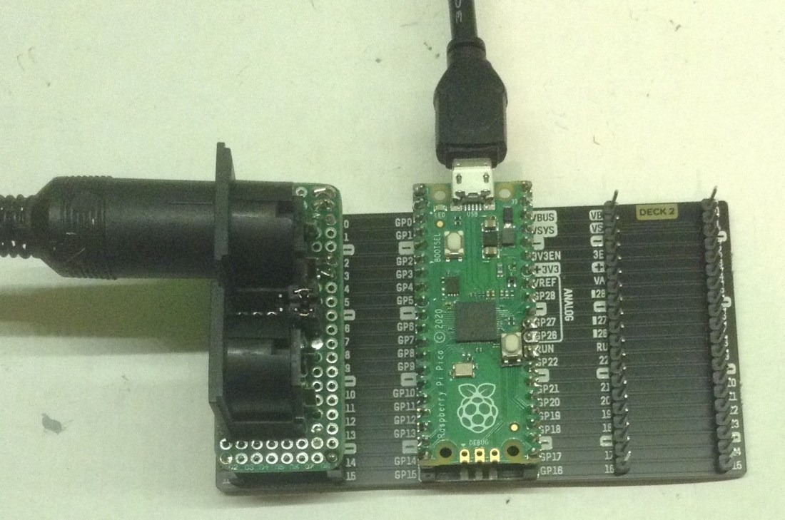
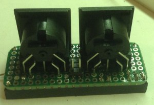
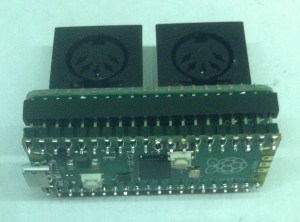
Here you can see the finished thing – first on its own, then with a Pico attached underneath. You can see it plugged into my Pimoroni expander in the photo at the start of this post.
The Code
There is no code with this project, but I’ve test it using Pi Pico PIO Poly Tone MIDI Keyboard for MIDI in and MIDI, MicroPython and the Raspberry Pi Pico for MIDI out.
Closing Thoughts
Although once again I feel compelled to apologise for my dodgy soldering, and the “dead bug” approach is far from ideal, I’m actually quite pleased with this as a prototype.
It is the kind of thing I could imagine using as a test-bed to try my hand at PCB design. But if I’m truthfully honest, what I’d really like is for those clever folk at Pimoroni or Adafruit to do it properly and make an “off the shelf” version for me to just use.
Kevin

Would you consider designing a PCB for this?
LikeLike
I did think about making one in this style, but in the end went with the following: https://diyelectromusic.wordpress.com/2022/07/19/raspberry-pi-pico-midi-module-pcb/
I’ve also got some modelled on the Pimoroni dual extender.
I might still have another go at this one, but I think it would need surface mount components to all fit, and that isn’t something I’ve really done so far.
Kevin
LikeLike
Yes, I have already built several Pico MIDI boards using your other PCB designs! I just recently got a quad extender with a rechargeable battery and thought it’d be nice to have a MIDI pack on there with my audio pack. I wanted to be able to attach a micro SD card reader, too (which I couldn’t do with your other boards). Thanks for considering it.
Peter
LikeLiked by 1 person
It’s still on the “todo” list – largely as it feels like unfinished business rather than because I’d particularly need one 🙂
I did ping a few companies via social media to see if anyone fancied making one, but no one picked it up. I even wondered if it would be simpler to do a feather to Pico converter to allow me to use the Adafruit MIDI feather wing… but it just doesn’t quite fit!
Kevin
LikeLike
Ok, so I’ve had a go but basically it doesn’t fit in the Pico’s two-header footprint… but maybe taking a file to a DIN socket it might work…?
https://mastodon.social/@diyelectromusic/112534781703710001
Kevin
LikeLike
Thanks for trying…is it that the DIN sockets will fit too tightly against the tips of the header pins? The sockets that Adafruit sells don’t have the three flanges on the backside…would that help? I also wondered if the board might be T-shaped so that the DIN sockets point in the same direction as the USB connector on the Pico.
LikeLike
I have some of those without the extra plastic at the back, so that should be ok – yes it is more if the overlap of the front with the soldered headers will be a problem. I’m going to give it a go regardless and see how it comes out 🙂
I’ve also included a footprint for MIDI TRS instead, as long as a slightly “off-board” PCB mounted TRS socket is used. I have some on order, so watch this space.
There are many options for shapes, which I think is why I went with the Pico version I did before – having MIDI alongside the Pico.
Kevin
LikeLike