After having some fun with my Arduino MIDI VS1053 Synth I wanted a few more synth modules to play with and found some cheap ones online. But when they turned up, it turns out they are not VS1053 breakout boards (which I’m pretty sure they said they were), but used the VS1003 instead.
Here are the follow-ups for this project:
This project describes how I set to work getting them going.
Warning! I strongly recommend using an old or second hand keyboard for your MIDI experiments. I am not responsible for any damage to expensive instruments!
These are the key Arduino tutorials for the main concepts used in this project:
If you are new to Arduino, see the Getting Started pages.
If you want a simpler solution to having a MIDI/MP3 module for use with your Arduino, see the Arduino MIDI VS1053 Synth project and I’d recommend one of the Adafruit or Sparkfun shields for the quickest “out of the box” experience.
Parts list
- Arduino Uno
- VS1003 based breakout board
- 10K potentiometer (optional)
- MIDI receive circuit (see Arduino MIDI Interfaces)
- Breadboard and jumper wires
The Circuit
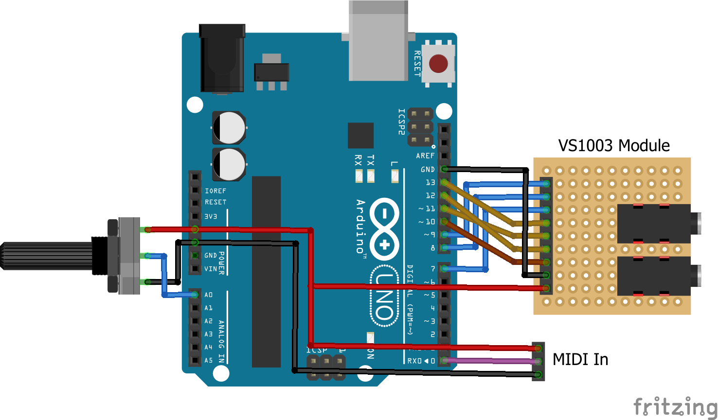
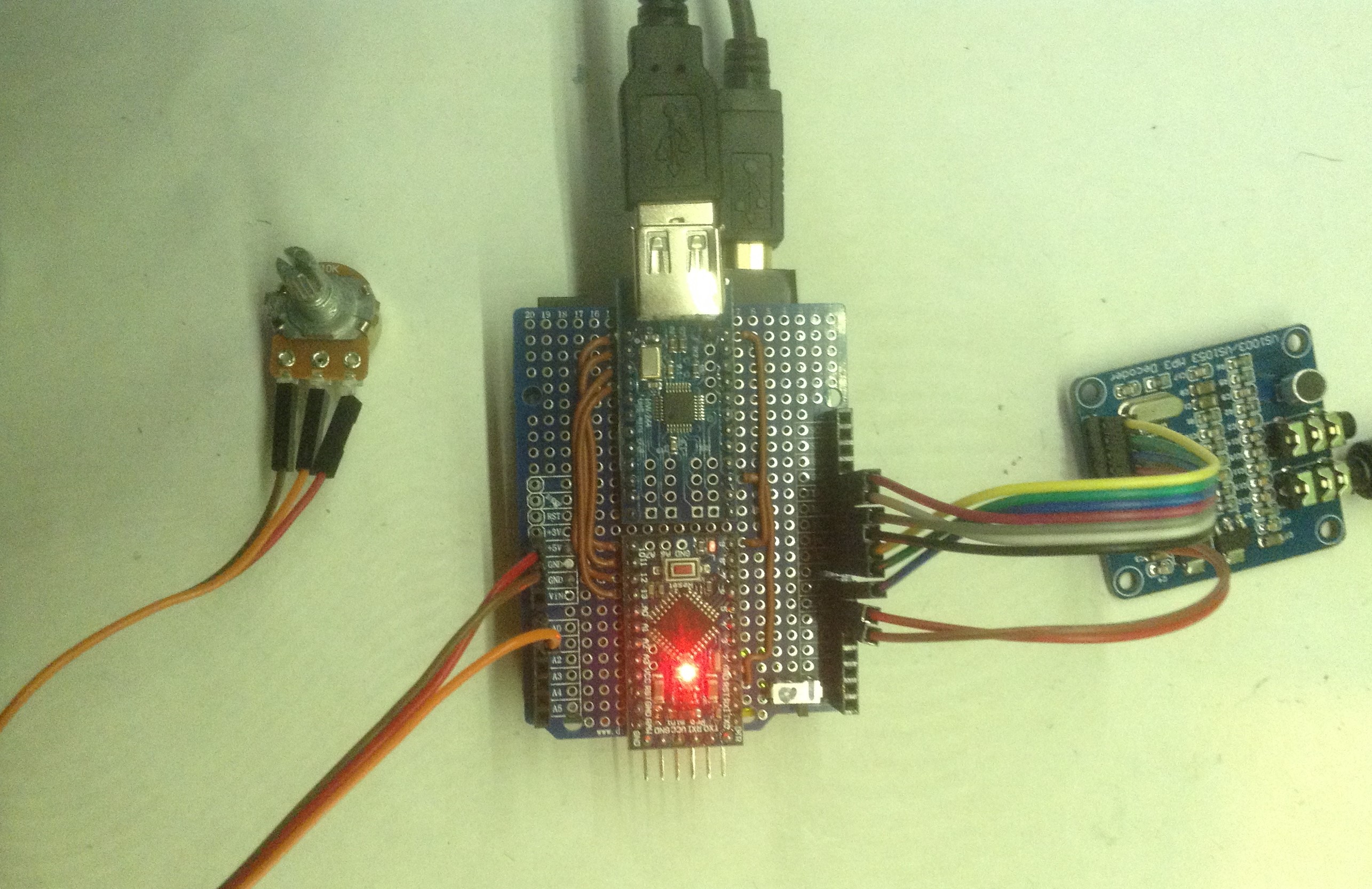
The VS1003 module that I have looks like the following and is labelled “VS1003/VS1053 MP3 Decoder”.

The MOSI, MISO and SCK pins are linked to the Arduino’s SPI hardware pins, 5V and GND to power, and the rest to digital IO pins. As I mentioned previously, I’m not particularly clear about the voltage levels on the IO pins, but I’ve followed the lead of the UNO-shaped shield, and just directly connected them to the Arduino.
The full mapping I’ve been using is as follows:
Arduino                VS1003
   9                    XDCS
   8                    XCS
   7                    DREQ
  13                    SCLK
  11                    MOSI
  12                    MISO
  10                    XRST
 GND                    GND
  5V                    5V
 As an optional extra, I added a potentiometer connected to the Arduino analog input A0 to allow me to select the different voices of the VS1003.
I also added a MIDI receive circuit (in my case using my USB host shield, but you could use any of the Arduino MIDI Interfaces) to the Arduino’s RX.
As I was running out of 5V links, I’ve used two of the digital IO pins as 5V and GND for the module. There is some optional code to make the 5V IO pin “HIGH” and the GND IO pin “LOW” to allow them to power the module.
Arduino                VS1003
   5                    GND
   6                    5V
The Code
This project has been a long time coming and there were a number of things related to this module that caused me trouble, but I’ll expand on those later (if you’re curious), but for now, here is the walk-through of the main features of the code required to drive this module.
Like the VS1053 previously, this module needs some special code installing over the SPI bus when it starts up to enable the real-time MIDI mode. I found a few “quick hacks” that allowed this to happen with the VS1053, but no such things exist for the VS1003. Instead I sought out and installed the official VLSI “Real Time MIDI Application” (which can be found here).
On downloading the “rtmidi12.zip” file and expanding its contents, you get the following:
- code
- rtmidi1003b C, BIN, PLG, COM files
- rtmidi1033c C, BIN, PLG, COM files
- rtmidi1053b C, BIN, PLG, COM files
- docs
- rtmidi.pdf
I grabbed the rtmidi1003b.c and rtmidi1053b.c files and copied them over to my Arduino sketch and renamed them .h files. These are original C files (now C header files), not the default Arduino CPP files.
I wanted the code to support either the VS1003 or the VS1053, so at the top have a way to select which chip I’m using:
// This code supports several variants of the VS10xx based shields.
// Choose the appropriate one here (and comment out the others).
//
//#define VS1053_MP3_SHIELD 1
#define VS1003_MODULE 1
Update: This code has now been validated for both VS1003 and VS1053 support. See here for further details: Arduino MIDI VS1003 or VS1053 Synth.
Then I can use this to choose the correct rtmidi files as follows.
#ifdef VS1003_MODULE
extern "C" {
#include "rtmidi1003b.h"
}
#endif
#ifdef VS1053_MP3_SHIELD
extern "C" {
#include "rtmidi1053b.h"
}
#endif
I did have to make a couple of minor changes for my code though. I thought CODE_SIZE and atab[] and dtab[] (the two lists of magic numbers defined in the VLSI code) weren’t very descriptive so I renamed them in my own files as follows:
#define VS10xx_CODE_SIZE 527
const unsigned char vs10xx_atab[527] PROGMEM = { /* Register addresses */

};
const unsigned short vs10xx_dtab[527] PROGMEM = { /* Data to write */

};
I also had to add the PROGMEM keyword so that the numbers were programmed into the Arduino’s program memory, otherwise they would be too big to load into the Arduino.
This results in my code now having two lists of magic numbers – vs10xx_atab and vs10xx_dtab, one a list of addresses to write to, and the other the list of values to write. This is used in a routine later to load the magic numbers into the VS1003 over the SPI link to enable the real-time MIDI mode.
Another file I used was vs10xx_uc.h which I also downloaded from the VLSI website here. This contains a number of useful definitions for interacting with the VS10xx series chips.
Armed with all this it was now possible to start talking to the module and see if I could get it doing anything. To cut a long story short, yes, it can now act as a General MIDI module in the same way as the VS1053, but with a more limited set of instruments available.
Advanced Discussion
There were a number of challenges on the way to getting this working.
First, I had a couple of bugs in my own code that I was using to read the mode and status registers of the VS1003. I ended up reading a 16-bit mode register into an 8-bit value, but then printing it out to the screen as a 16-bit value again. This meant that the top 8 bits were always wrong, and sometimes showing nonsense. This led me to wonder if the boards themselves were actually faulty at one point (in fact I re-soldered all the discrete components on one board to be sure there were no faulty solder joints)!
Moral: Be really sure your test and debug code is working properly!!
Second, I was getting no-where getting the MIDI working and couldn’t work out why. With the confusion over the mode, I did wonder if the chip was erroneously starting up in a different SPI mode to the recommended one. Essentially there are many ways you can talk to this device, with a mixture of different enable and select pins. The core SPI interface is really two SPI links: one for control messages (SCI) and one for data messages (SDI). These are enabled with their own “select” pins (XCS and XDCS in the code above), but there are modes to allow these to be shared and there are other “legacy” modes that use SPI in a different way again. The default mode should be SM_SPINEW (see the datasheet) but I wasn’t seeing that mode on startup. That was the 16/8 bit bug at work though. Once I realised I couldn’t trust my debug code and fixed it, sure enough the VS1003 was indeed starting in the right SM_SPINEW mode. So that was good, but it was back to square one on the MIDI front…
Then I noticed there was a TEST pin, so had a brief diversion making sure that was wired up correctly. Apparently there was a fault on some early Sparkfun boards where the TEST pin was left floating causing intermittent problems. But no, after hunting down schematics, sitting with a magnifying glass and the chip datasheet, and carefully probing, I decided TEST was indeed linked to IOVDD as it should be. There are a number of different power circuits on the module though which initially caused a bit of (more) confusion.
But having read about the tests built into the device I managed to enable one of the test modes of the VS1003 and got it to output a sine wave signal which means I knew that the SPI link and audio output was working. That in itself was useful as these boards have two sockets – “Line In” and “Phone”. The output is the “phone” socket…
Now I was starting to wonder if there was some data missing in the magic code being loaded or if there was some problem getting it all over the SPI bus. Eventually I noticed a line in the rtmidi application note:
1.2 Loading Through SCI
The software can also be loaded through SCI in the same way as all patch codes. The
application loading tables and plugin files are available in the code/ subdirectory. After
the code is loaded, it is started by writing 0x30 to SCI_AIADDR (0x50 for vs1053b). The
code clears SCI_AIADDR automatically after start. To return to normal decoding mode
give a software reset.
It turns out that the code itself will not run until the start address is written to the SCI_AIADDR register. My code wasn’t doing this. Adding in that extra register write did the trick. I finally had real-time MIDI working.
I was slightly puzzled though as I do have working VS1053 code, but on re-examining the previous project, it turns out that it was using a much simpler plug-in (as I knew it was), but at the end of the plug-in were some magic numbers which automatically updated the SCI_AIADDR register (register 10) to the correct value as part of the upload process.
VS1003 Instruments
One final quirk of the VS1003 is that it doesn’t have a full General MIDI Instrument set, but it does have 14 voices that approximate to a full GM voice set. The data sheet lists the following voices, but says nothing about how they map onto the GM set.
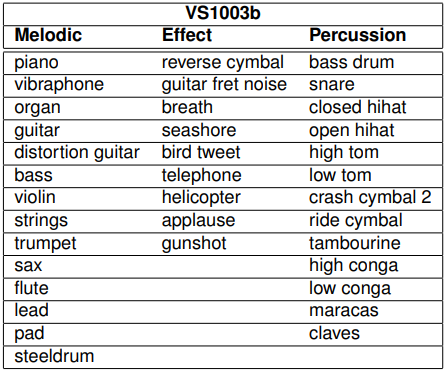
In principle I guess if you are just playing MIDI files or sending MIDI program change messages to the module, then you just need to know it has something against each of the GM instrument numbers and accept that your “trombone” might sound a bit “trumpety” leave it at that.
But if you want to choose one of the VS1003 voices directly, you really need to know which voice numbers choose the different instruments for you, but this information doesn’t seem to exist on the Internet. So I wrote some code and had a play around with a MIDI controller and worked them out.
The result is the vs1003inst.h header file in the source for the project, which now has definitions for the VS1003 specific voices.
There was one last hurdle though (this module was really out to get me I think). It turns out that the MIDI specification lists instruments using the numbers 1 to 128. However in MIDI messages this has to be translated into the values 0 to 127. I know this and have had to account for it a number of times already in previous projects.
But what about the drums? The same MIDI spec lists drum numbers too: 35 is “Acoustic Bass Drum”, 60 is “Hi Bongo” and so on. These are supposed to map onto MIDI note numbers used on MIDI channel 10 (again MIDI channels are 1 to 16 in polite conversation, but 0 to 15 “on the wire”)… so when it comes to sending a bass drum “note” are we sending 35 or 34? I.e. is the MIDI drum voice list also a 1 to … list? Or as MIDI notes are already 0 to 127 (“C” is 60 when talking about it and when sending it “on the wire”), is the drum list already a 0 to … list?
I can’t find anywhere that tells me explicitly.
In fact, the Internet seems somewhat confused about the topic too. In reality I’m pretty sure MIDI drums are on the 0 to 127 scale, so they are already in “on the wire” format (and Wikipedia seems to agree – at least at the time of writing). But I’ve also seen a number of what appear to be comprehensive MIDI reference articles that imply the 1 to … numbering.
0-indexing:
1-indexing:
Your guess is as good as mine:
I’m going with the 0 to … version which I’m pretty sure matches my personal experiences so far and seems backed up by practical experiments (i.e. me, some synth modules and MidiOx spending an hour together).
There are also some common extensions to the range – the original General MIDI percussion list defines instruments on MIDI notes (I’m going with the “MIDI note” view now) 35 to 81. But it seems pretty common to expand that out from 27 to 87, and the VS1003 does indeed respond to the wider range.
So that was an unexpected source of confusion just when I thought I’d worked out all the issues!
Closing Thoughts
My original aim was to have a few cheap VS1053 modules kicking around I could play with having thought I’d already worked out all the issues. This was about as far away from that as it was possible to get! The wrong chip; debug code bugs; problems setting it up; right up to confusion in the MIDI spec itself (at least confusing to me anyway).
But I’m pleased to have got there in the end. I now need to decide what to do with these modules – I have three! The first step is probably a simple shield to lose all the wiring.
Also, now that I know so much more about these devices, there is so much else they can do. I would really like to have a proper look at all the additional patches and applications that can be loaded into them and see what access to a neat audio-specific digital signal processor can really do for me. There is quite a lot of information in the VLSI forums on the topic too.
I’d have never seen all that potential without the challenges that getting this working has brought. So all is good.
Kevin

Parabéns! Grande trabalho! Obrigado por compartilhar!
LikeLike
Thank you!
LikeLike
Great project! Last year, I ordered some VS1053 boards to try them as crude General Midi Synth on sound cards. Of course, it was populated with VS1003 instead. I managed to have it boot the midi sample from an EEprom after some hackery. It would not play though. Your project however with an Arduino inbetween works fine when connected to a SB Vibra 16 gameport. Duke3D sounds not bad using a VS1003 as GM synth 😉 I just have to get rid of some random notes/instruments inbetween. I suspect the Arduino’s RxD gets noise from somewhere.
LikeLike
That’s great to hear! Do let me know if you get any further with the random notes/instruments – it may be that the VS1003 doesn’t have a clean mapping over to GM. Maybe its an odd extra percussion track or something?
It may be possible to build in some extra filtering on the Arduino end? I can’t remember if the MIDI handling allows software MIDI THRU or not, but it might be worth hooking your soundcard up to a different MIDI project to see if you get the same kinds of odd effects?
Alternatively, something like my “Arduino MIDI Logic Analyser” on a second Arduino might give you a clue? (see: https://diyelectromusic.wordpress.com/2021/06/08/arduino-midi-analyser/)
Either way, do let me know how you get on.
Kevin
LikeLike
Those glitched notes were definitely random. The glitches were different with each playback of the same song. I’ve swapped the SB Vibra16 for some Yamaha based ISA card and that one works perfectly without any glitches in the playback!
The VS1003 doesn’t sound bad in those games I’ve tried (Duke3D, DoomI+II). I mean it is certainly not a Dreamblaster or SoundCanvas, but it is not unpleasant to listen to. I have to get a VS1053 to compare it to some day.
Maybe the Vibra is not entirely MPU-401 compatible anymore.
There is only one little problem left: With Duke3D, the VS1003 playback begins with starting up the game and it ends without hanging notes when I leave the game. Every time. But with the Doom based games, I need to reset the Arduino Nano while the game is running for the VS1003 to play anything. This is necessary every time. And when I leave the game, the last notes played often hang. I noticed that it seems to receive MIDI data before the reset as the the RxD LED is flashing as usual, but the MIDI LED that I’ve hooked up is not flashing in this case. I’d say the MIDI library is probably discarding the serial data in MIDI.read() for some reason, and it stops doing that when I push the Arduino’s reset button.
For debugging, I really would like to be able to take the project as it is and somehow trace both the serial data received and the SPI data sent. As far as I can see, your project and the MIDI library should work on a bluepill board without major issues. It has the advantage of 3 UART and 2 SPI peripherals and more than enough horsepower for some tracing during playback.
LikeLike
When I’ve needed more serial ports, I’ve used a Pro Mega 2560 board, which is like an Arduino Mega but in a smaller (and cheaper) form factor. That has four serial ports. I don’t think I’ve used anything ATmega328 specific in my code for this one, but I can’t remember off the top of my head. Another option might be to SoftwareSerial the MIDI and add some debug traces…. anyway, keep me in touch with how you get on!
Just out of interest, are you using a 15-pin joystick/MIDI adaptor or hooking things up some other way?
LikeLike
Another thing that might be worth a try – by default the MIDI library only processes a single byte at a time, and then only returns data from MIDI.read() when it has a full message. You can change this behaviour by setting Use1ByteParsing = false when setting up the MIDI library. Details of how to do that can be found here: https://diyelectromusic.wordpress.com/2020/09/14/mozzibyte-output-board/
This would mean the processor spends more time per loop() doing MIDI which may or may not make a difference…
LikeLike
btw – if you are building sound cards for gaming, have you come across the MT32-Pi project? See: https://diyelectromusic.wordpress.com/2021/03/01/raspberry-pi-clumsy-midi-and-mt32-pi/
LikeLike
Getting your project to run on a Bluepill was pretty straight forward. Just redefine SPI, MIDI Serial and pins and use the by-64 SPI clock divider.
from MIDI: ->
to VS1003: B0 7 58
B1 7 58
B2 7 58
B3 7 58
B4 7 58
B5 7 58
B6 7 58
B7 7 58
F0 41 F0
41 midi msg invalid type
10 midi msg invalid type
42 midi msg invalid type
12 midi msg invalid type
40 midi msg invalid type
0 midi msg invalid type
7F midi msg invalid type
0 midi msg invalid type
41 midi msg invalid type
F7 B0 79 0 B0 7 78 B1 79 0 B1 7 78 B2 79 0 B2 7 78 B3 79 0 B3 7 78 B4 79 0 B4 7 78 B5 79 0 B5 7 78 B6 79 0 B6 7 78 B7 79 0 B7 7 78 B8 79 0 B8 7 78 BA 79 0 BA 7 78 BB 79 0 BB 7 78 B9 79 0 B9 7 78 C9 0 B9 7 64 B9 A 40 99 23 7F B9 7 64 B9 A 40 99 28 7F C0 0 B0 7 64 B0 A 40 90 8 7F C1 2F B1 7 64 B1 A 40 91 20 7F C2 33 B2 7 64 B2 A E 92 20 7F B2 7 64 B2 A E C3 33 B3 7 64 B3 A 72 93 26 7F B3 7 64 B3 A 72 C4 5E B4 7 64 B4 A E 94 2F 7C B4 7 64 B4 A E C5 5E B5 7 64 B5 A 72 95 35 5C B5 7 64 B5 A 72 C6 75
…
Doom2 (plays nothing, but does forward to VS1003):
==================================================
setup() done
-> F0 7E 7F 9 1 F7
B0 79 0
B0 7 64
B1 79 0
B1 7 64
B2 79 0
<- B2 79 0
If I ignore MIDI messages with cmd=0xF0 in loop() and don't send them to the VS1003, then Doom2 Music starts working fine. It looks like I have to find out what these 0xF0 MIDI messages are about and why the MIDI library is not able to parse them correctly.
LikeLike
Oh no wordpress messed up the whole text. I’ve placed it here:
http://watz.at/midilogs.txt
LikeLike
Hello, I have a problem. The code seems to compile, but there is no sound and it does not accept midi. Please send the compiled binary file to my email. antoh0grishino@gmail.com
LikeLike
I’m afraid there is no binary, what you see is what there is – I only have the sketches to share.
Kevin
LikeLike
OK after a quick check: 0xF0 are SysEx messages that can be of variable length. They start with 0xF0 and end with 0xF7, and the bytes inbetween must not have bit 7 set. Sounds easy.
Duke3D doesn’t seem to send any SysEx messages on startup. Everything works fine.
Doom seems to send a malformed SysEx message of “F0 41 F0 41 10 42 12 40 00 7F 00 41 F7” on startup. That totally messes up the MIDI library parser and nothing gets sent to the VS1003 anymore.
Doom 2 sends a SysEx message “F0 7E 7F 09 01 F7” on startup, which is at least well formed. However the data that gets sent to the VS1003 is “F0 06 00”, which is a malformed SysEx message. I’m pretty sure the sketch simply cannot handle SysEx and that is why garbage is being sent to the VS1003. Somehow that malformed message seems to make VS1003 ignore all further (valid) MIDI messages until reset.
I wonder why no other synths have problems with those Doom/Doom2 SysEx messages.
LikeLike
The MIDI library will return a MIDI channel of 0 (usually they are 1 to 16) if it receives a SysEx message, although of course it could check the MIDI command itself too…
I have a line of code that says “always pass on SysEx messages” as follows:
if (ch == 0) ch_filter = 0xffff;
If you wanted to filter them out you could change this to:
if (ch == 0) ch_filter = 0;
I am assuming here that the MIDI library parser is keeping track of the MIDI command byte of course, and setting the channel appropriately whilst still in SysEx mode…
I seem to recall one of the reasons for updated VS10xx code was something to do with better SysEx handling, but I think it is using the latest code from VLSI already. I have noted one or two oddities though – when sending over patch numbers, I’ve had to send a “dummy” MIDI command otherwise the last one wasn’t being registered… so I could easily imagine there might be other weirdness going on!
Looking at your MIDI log it is interesting to see that in all three cases we can see a MIDI control change on “controller” 7 for every channel, which is the master volume (e.g. B0 07 58). In the second two cases we can also see the command to “reset all controllers” (e.g. B0 79 00).
It is curious to note that even in the Doom case, these commands are there, but as you say the weird SysEx handling seems to have confused things somewhat.
I’m really not sure different bytes are sent to the VS1003 compared to what was received when processing a SysEx sequence, but obviously don’t know quite where your debug statements are in the code. I suspect the code is assuming a two or three-byte message each time whereas SysEx messages are multi-byte, so on that basis, maybe the better version of the “ignore SysEx messages” code would be to put the talkMIDI call within the IF statement checking for channel messages:
if ((cmd >= 0x80) && (cmd <= 0xE0)) {
// Merge in the channel number
cmd |= (ch-1);
talkMIDI(cmd, MIDI.getData1(), MIDI.getData2());
}
Then you could add an else for handling SysEx messages in a special way… there are special calls in the MIDI library to handle SysEx messages – see: https://fortyseveneffects.github.io/arduino_midi_library/a00033.html#gac1c9d068800507aaa262e9be8b0cbb85
There isn't really much intelligence in my MIDI forwarding code, so it is perhaps a little too simplistic… one option might be to include more of a proper MIDI message state-machine or at the very least some intelligence in understanding the MIDI commands, as described here: https://diyelectromusic.wordpress.com/2021/04/25/arduino-midi-filter-revisited/
There is a slightly more complex MIDI parser here – https://diyelectromusic.wordpress.com/2021/06/13/raspberry-pi-pico-midi-channel-router/ – but it is in micropython for the Raspberry Pi Pico, but the python code can act as useful "pseudocode" for a C version if you fancy getting adventurous!
But I think filtering out SysEx messages is probably the thing to do for now. I suspect there won't be many systems sending VS10xx SysEx messages!
Kevin
LikeLike
I’m getting closer 😉
The SysEx message that Doom sends is a Roland GS “reset” command. It does however have the first two bytes duplicated, which is a major problem for the MIDI parser. I have to dig deeper to find the source of these two extra bytes.
The SysEx message Doom2 sends is a GM “reset” command.
LikeLike
Hi there! Glad to see you’re making progress 🙂 I’ve been away for a while, but will take another look at the sketch. It really doesn’t surprise me to hear that SysEx messages might mess things up! I’ll get back to you 🙂 Kevin.
LikeLike
I’ve updated the code to remove all SysEx messages. The function talkMidi has no concept of messages that aren’t one or two data bytes long, so for now no SysEx message handling (cmd 0xF0 or greater) is done at all.
LikeLike
This is great project.. thanks for this..
But i have a problem, i don’t know what happened to my vs1003.. for the first time it was work properly with amplifier 12v then after some time now the sound it’s disappeared.
And sometimes the sound is back again and then now it’s disappeared no sound anymore.
Can you suggest me what happened with that?
LikeLike
I’m sorry that’s very hard to “debug” from here without a bit more information. If it was me, I guess I’d try some of the following (apologies if you’ve already done these and I’m stating the obvious to you):
a) double check your audio path (lead and amp, etc) with a different source.
b) check voltages around the 1003 to make sure it is getting the right power in the right places.
c) maybe try a different power supply to your Arduino (I’m assuming you’re using it with an Arduino)
d) try to get the 1003 working with some common code.
e) I seem to recall there is a test mode (at least for the 1053, maybe the 1003 is the same? I can’t quite remember!) where it will just output a sine wave with no other processing, so you can check the audio path. Maybe try with a different audio lead/amp too.
That’s all that springs to mind right now I’m afraid. As I say, its a little hard to suggest more concrete things without knowing a little more about your circuit/setup/etc…
Good luck!
Kevin
LikeLike
thank you so much, and don’t appologies cause it’s not your project fault but it’s because my vs1003 board. i tried example sketch with vs1003 hello and same no sound.
i fixed with just connect 3.3 volt to pin 44 ‘rcap’ for a while maybe just 1 or 2 seconds and the sound is back but will back with no sound after some minutes and i give 3.3 volt to that pin 44 and back again.
sorry for my bad english
btw how to choose or to active drum channel or percussion ?
LikeLike
Sounds like you’re already way beyond my knowledge of how these devices work! I’m not really an electronics person 🙂
Are you making your own board? I noticed that Waveshare do a vs1003 board and publish their schematics, so I don’t know if that helps?
I think when in MIDI mode it will automatically respond on channel 10 for percussion, but it’s been a while since I’ve played with a vs1003. I’ve now gone back to my cheap vs1053 modules.
Kevin
LikeLike
no im not make it, i bought it and yes i checked from the scematic but there nothing is wrong with that, i was just thinking if the ic need something to wake it up.
Yes you are right it automatically respond to percussion i tried your arduino piezzo midi controller sketch and it’s work.
thanks for all, i appreciated your great works
LikeLike
Please send your discord to my email so that I can contact you and help me please antoh0grishino@gmail.com
LikeLike