When I first heard about the Microrack concept, I was still playing around with my own Educational DIY Synth Thing so naturally I was really interested in seeing what it would be about. That was back-end of 2024. It has taken until now to realise that from the original Kickstarter.
Now that I have one in my possession, are are a few notes about it as I start to play.
What Arrived
I ordered the Synth Starter Kit and an additional Subtractive Extra Kit. This has given me the following modules:
- 1x USB-C power module
- 1x 3.5mm speaker/output module
- 2x VCO/LFO
- 2x High/Low pass VCF
- 2x AD EG
- 1x Noise + S/H
- 1x Clock Counter
- 1x Lo-Fi Delay
- 1x Stylus Keyboard
- 1x 830 point solderless breadboard
- 1x pack of “premium” jumper leads
One immediate surprise was that there was only one breadboard and no additional means to power it. The description of the Subtractive Extra Kit in the actual pledge did imply the add-on would include another breadboard but apparently once everything was costed out it just wasn’t feasible.
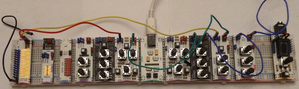
But in reality, as these are standard breadboards and wires, extending it is as simple as connecting the power rails together between two breadboards. In fact that isn’t even necessary if the power module is placed in the middle across both boards, as shown in my photo above. So I just added another 830 point breadboard myself and got started.
First Use
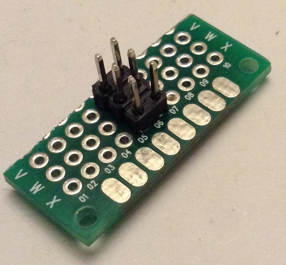
Before the first use, I took their advice and “primed” the solderless breadboard. I soldered up a quick “jumper pin pusher” as shown below to push into each of the power rail pin holes to ensure the modules can be inserted easily.
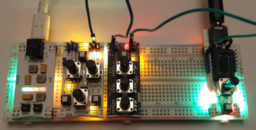
My first attempt used a USB power hub and USB-C lead. The first visual impressions are great – the LEDs lighting up through the PCBs look really good and make for very pleasing visual feedback on what is going on.
Everything worked fine to start with, when there was just an oscillator and output. But when adding the filter and second oscillator as a LFO, I soon found that certain combinations would cause a power-out. It turns out it is really easy to overload a typical USB power pack once there are a few modules running.
I switched to a Raspberry Pi 4 USB-C power supply, which is rated at 5.1V / 3.0A. This works really well and I’ve not had any power issues since even with all modules powered up.
It is curious that the system only uses the four power rails of the breadboard. This introduces a few limitations:
- Modules can’t be placed absolutely anywhere – the breadboards have gaps where there are no pin holes so you have to place modules accordingly.
- Modules have to be placed to span the middle gap, as that has no continuity in the tracks, otherwise some jumper wires are required.
- The rails are not symmetrical – they provide +5V, -5V, +12V and GND so it is important to know which is which!
The idea, as I understand it, is to allow prototyping of additional circuits on the breadboard itself. But for most cases, the centre blocks of pin holes are ignored.
A basic oscillator – filter – output synth chain is easily put together and can be continuous driven or driven via CV from the stylus keyboard.
And this was where I hit the first hints of the limitations of the choice of provided modules.
Module Selection
The more I think about it, the more the choice of modules for the Synth Starter Kit seemed a little odd at first.
When adding in the stylus keyboard, it has a GATE and CV output. CV to the oscillator is obvious. And naturally the GATE would probably be expected to go to an envelope generator.
But there is no VCA! I have a Lo-Fi delay module and an audio output module, but no other means, as far as I can see, of applying an envelope to an amplitude.
The clock module is also a bit of a mystery. First of all, it isn’t actually a clock but takes a clock input and uses to drive 8 GATE outputs, so to my mind that makes it a clock-driven gate sequencer. But there is nothing to generate a clock directly and I have nothing to trigger off 8 GATE outputs.
Similarly I’m struggling at this stage to know what to do with the noise + S/H module. With no EG-driven VCA the noise outputs make little sense, and I’m not quite sure how to drive the S/H module.
Enlightenment Dawns…
At this point I took a proper look at the two provided “cheat sheets” that came with the system and things start to make a little more sense.
There is a “Bass and Drum” patch that shows how to use the LFO as the clock with a reset after four steps, triggering the EG on step one and noise via the S/H on all four steps. The EG is driving the filter and you get a pretty quirky noisy pulse with a nice “pew” on every fourth step.
I’m not entirely sure what “Jacuzzi + The Drone” was all about – that just seemed quite a few farty noises that I couldn’t get to do anything interesting (to me). I might have to give this another go later.
“ARP Lead” shows how to use the EG as a clock source and the GATE sequencer to drive a pitch level on certain steps of the clock. It also shows how the stylus can be used to set the base pitch for the sequence.
I’ve also played with using the clock module as a frequency divider to get a sub-octave.
At this point, we can see how creative use of the modules starts to show how the components can come together for something interesting.
Good Points
The modules do seem very full-featured. The oscillator for example, has VCO and LFO modes, with three output waveforms and the option for FM. It also has an option for -5V to +5V or 0 to +5V to support full audio output or use as a CV for other modules. I’m not entirely sure I understand at this stage what all the LEDs are telling me, but I guess I’ll figure that out.
There are some nice conventions too: blue headers for inputs, red for outputs, for example. And it is obvious some modules are designed for plugging next to each other.
The use of jumper wires makes for very easy integration with other things, so I’m looking forward to seeing how I can hook it up to my Volca Modular and my Educational DIY Synth Thing.
The modules are fully open sourced and documented online here: https://github.com/microrack/modules
The PCB design is very neat and tidy and seems quite a master of minaturisation.
The electrical specification is pretty complete with lots of features designed for robust protection when using with other devices. All provided modules have protections for shorts, reverse polarity, over and under voltage, and so on. There is also a lot of care taken over how to support chained inputs and duplicate inputs and outputs.
The mechanical specification is also fully published. All details here: https://specs.microrack.org/
In short, once you get stuck in, everything seems very well thought out.
Some References
There is a lot of documentation, so here I’m listing a few interesting odds and ends I’ll want to refer back to (and almost certainly will have forgotten where I found them).
Power – from https://microrack.github.io/docs-test/ecosystem/20-power/ – listing top to bottom
- +12V
- +5V
- GND
- -12V
Signals – from https://microrack.github.io/docs-test/ecosystem/50-compatibility/
- Audio: +- 5V – 10Vpp
- CV: 0 to +5V
- Pitch CV: 1V / octave
- GATE Low < 0.7V
- GATE High > 3.5V
Conclusion
My initial hope was for use in an educational setting, but I’m not sure the bare PCB approach would be up to that. I don’t know if there would be ESD issues, but I do think that repeatedly plugging in and out of the breadboard would eventually take its toll on the power pins. Also, I think it would be far too easy to get the power connections either shorted or mixed up, especially if creating prototype additional circuits.
As a functioning synth for my own messing about, I’m going to have to invest in a couple more modules I think. I will need at least one mixer/VCA, and probably one of the headers-to-jacks modules too. On the main site, it still lists modules as for pre-order – I suspect that is because the Kickstarter units are still on their way to backers.
I wasn’t originally interested in MIDI to CV or the microcontroller DIY board, as I figured those would be fairly easy to do myself. And whilst that is still the case, I’m still wondering about their addition to create more of a stand-alone setup to play with.
It is interesting to note that there is a Eurorack mounting kit, but it is quite expensive, so I’m not sure I’m too fussed about that myself. But I might attempt to knock up some kind of 3D printed frame for housing a couple of modules. In fact, some users in the Microrack forums have done exactly that.
On balance, this is a very well thought out kit in general terms, but I think the choice of initial modules has veered towards the “beat box” rather than actual synth, but that is perhaps just my preference. But the three sample patches, and some of the ideas starting to appear in the forums, do show the potential of even what I already have.
At this stage, I’m looking forward to some proper playing around and I plan to digest some of the design information to see what I can do with the DIY side of the kit too.
I haven’t talked about the audio of course. It is pretty Lo-Fi, which fits right in for me of course.
There are already a number of videos up online from people far more knowledgeable than me, showing it in action. So I’ll leave it to those to show what it can do audio wise.
Like many systems, I think this will reward any time spent getting to know it and what the modules can do.
Kevin
