Over on my other blog, I spentt a fair bit of time looking at the TD4 4-bit CPU. One of the things I wanted to do with my NAND Oscillators and Logic Sequencer PCB was hook up the address/select pins to something else. And with three select pins, allowing the choice between 8 notes, what better to connect it to, than a 4-bit CPU?
Warning! I strongly recommend using old or second hand equipment for your experiments. I am not responsible for any damage to expensive instruments!
If you are new to microcontrollers, see the Getting Started pages.
Parts list
- Built TD4 CPU
- Built NAND Oscillators and Logic Sequencer PCB
- 5V power, jumper wires, amplifier, etc.
The Setup
The most obvious thing in my mind, is to hook up three of the four outputs to the three selection pins of the NAND sequencer, so that is what this post explores.
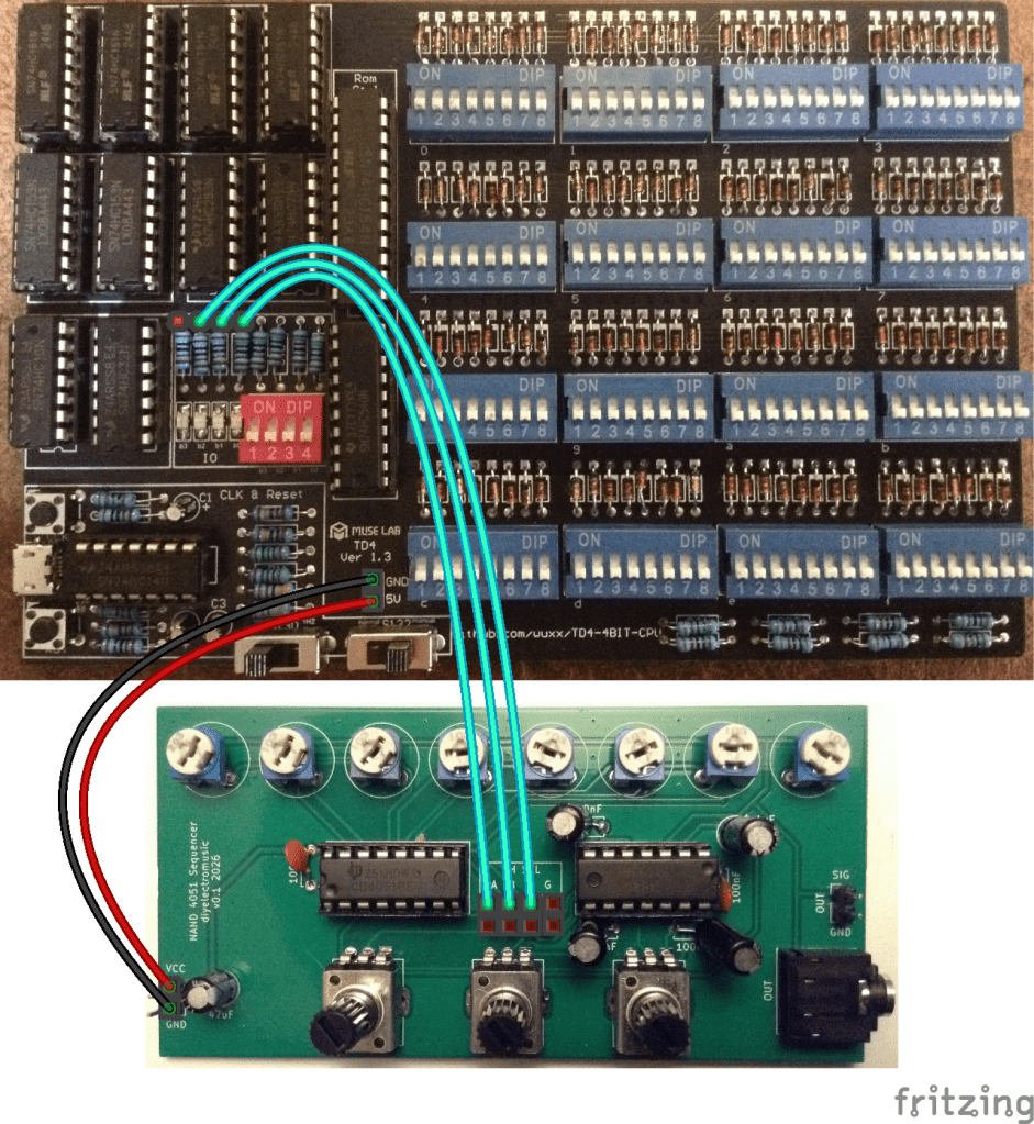
The NAND PCB needs the jumpers removing, which disconnects the pot-driven oscillators. Then the three select/address lines can be connected to three of the four resistors supporting the OUTPUT LEDs of the TD4, as shown above.
It is also possible to use the POWER header pins to power the NAND PCB too.
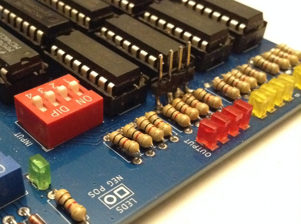
Any of the variants of TD4 I’ve built could be used, but I’ve shown above where they would need to be connected on the original. In the end I actually soldered four header pins to the appropriate side of the resistors on my own PCB version of the TD4 as shown below. A bit crude, but it does the job.
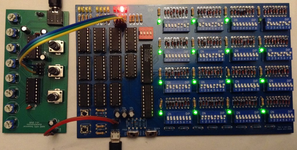
Connecting these over to the NAND sequencer and hooking up power gives me the following.
The Code
The simplest way to create a sequence is a set of OUT xx instructions where the least significant 3 bits (so values 0 to 7) map onto the three possible notes played by the NAND sequencer.
This is the simple LED OUTPUT code from Part 3 of my series, but this continually toggles between the lowest and highest notes.
0000 OUT 0001   # 1000 1101
0001 OUT 0111   # 1110 1101
0010 JMP 0000   # 0000 1111
A counter can be used to play all 8 notes. Note that in this code B will go from 0 to 15 (b0000 to b1111) but only the last three bits select notes. This means that the sequence will count from b000 to b111 twice for each pass through this loop with the top bit being ignored.
0000 ADD B,0001  # 1000 1010
0001 OUT B       # 0000 1001
0010 JMP 0000    # 0000 1111
There are only two speeds though, 1Hz and 10Hz so the above, which has three instructions, has a tempo of 20 bpm (1 note every 3 seconds) or 200 bpm (approx 3 notes every second). The tempo can be slowed down in steps of 1 second or 1/10 second by moving the JMP an instruction further down and back-filling with other instructions (ADD A,0 or b00000000 is a good one, and is essentially equivalent to a NOP).
The following code uses the INPUT as a counter in a loop to provide a partly configurable tempo.
0000 IN A        # 0000 0100    A = INPUT
0001 OUT B       # 0000 1001    OUTPUT = B                  # Plays the note in B
0010 ADD B,0001  # 1000 1010    B = B + 1
0011 ADD A,1111  # 1111 0000    A = A + (-1)                # Loops until A = 0
0100 JNC 0000    # 0000 0111    JUMP IF NO CARRY TO 0000    # Jump back to start for next note
0101 ADD A,0     # 0000 0000    Optional additional NOPs
0110 JMP 0011    # 1100 1111    JUMP to 0011                # Else keep counting
This is still only cycling through each note individually though, but that is kind of what an 8-step sequencer would do.
To get more creative with the programmability of the sequencer requires a series of OUT instructions and NOPs between them, for example:
0000 OUT 0000    # 0000 1101    OUTPUT = 0000 # Play note 000
0001 OUT 0010    # 0100 1101    OUTPUT = 0010 # Play note 010
0010 ADD A,0     # 0000 0000    A = A + 0     # NOP
0011 OUT 0001    # 1000 1101    OUTPUT = 0001 # Play note 001
0100 OUT 0100    # 0010 1101    OUTPUT = 0100 # Play note 100
0101 ADD A,0     # 0000 0000    A = A + 0     # NOP
0110 ADD A,0     # 0000 0000    A = A + 0     # NOP
0111 OUT 0110    # 0110 1101    OUTPUT = 0110 # Play note 110
1000 OUT 0101    # 1010 1101    OUTPUT = 0101 # Play note 101
1001 OUT 0011    # 1100 1101    OUTPUT = 0011 # Play note 011
1010 ADD A,0     # 0000 0000    A = A + 0     # NOP
1011 ADD A,0     # 0000 0000    A = A + 0     # NOP
1100 ADD A,0     # 0000 0000    A = A + 0     # NOP
1101 OUT 0111    # 1110 1101    OUTPUT = 0111 # Play note 111
1110 ADD A,0     # 0000 0000    A = A + 0     # NOP
1111 ADD A,0     # 0000 0000    A = A + 0     # NOP
This last programme is the one running in the video at the start of this post.
Closing Thoughts
I appear to have made a sound card for a 4-bit CPU 🙂
One thing I am quite keen to do is connect up the sequencer’s select pins to the TD4’s address lines, as I’d like to be able to have some incidental (accidental?) music that appears as a result of the CPU just running any other normal programme.
To do this I’d need to either hook into the output of the PC register or the input to the HC154 ROM decoder.
In fact, it would be really interesting to be able to hook up any sets of four signals – so the INPUT selector, or even the control decoding logic – just to see what it sounds like as the CPU is running normal code. That might require a special build of the CPU though.
I also have an address line spare of course, so it would also be interesting to use that to select between two NAND sequencers to give me a 16 step sequence.
Kevin
