I’ve had a bit of a play with logic based synthesizes in the past, but not in anger. However I’ve recently picked up “Make: Electronic Music From Scratch” by Kirk Pearson from Dogbotic.
It is excellent and a good chunk of that is based on circuits using the CD4093 Quad NAND chip, so I’ve started messing around properly with that again for a bit.
Warning! I strongly recommend using old or second hand equipment for your experiments. I am not responsible for any damage to expensive instruments!
If you are new to electronics, see the Getting Started pages. Or better yet, buy their book 🙂
NAND Oscillators
As shown in the book, using a Schmitt Trigger NAND or NOT gate is a good, and relatively understandable, way to get a simple oscillator going. It is almost a “Hello World” of electronic music and has been covered and repeated all over the Internet!
Here are a few good references to dig into what is going on:
- Chapter 3 of the book.
- All About Circuits: “Exactly How Schmitt Trigger Oscillators Work”.
- Stomp Box Electronics: “Schmitt Trigger Oscillator Calculator”.
- Kristian Blastol: 40106 Hex Oscillator Bank – DIY Modular in a Week 1.1
Most circuits hook up a capacitor and potentiometer and there is an instant, tunable oscillator, but I’d like to see what is involved in generating specific frequencies, for a reason that might become clear later (in at least in a future blog post if not).
The All About Circuits page has a detailed breakdown of how the voltage, resistance, capacitance and frequency all relate to each other, and eventually, assuming a 50% duty cycle square wave, ends up with the following formula:
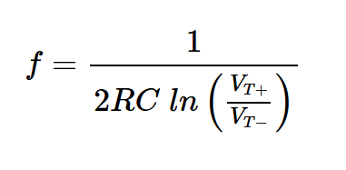
VT+ and VT- are the threshold voltages for the Schmitt trigger turning on and off. This will depend on the device in use, the supply voltage, and even the temperature (apparently) but for a CD4093, I’ve found the following extract of a datasheet:
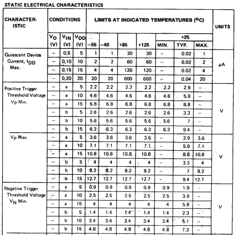
So taking the operation at 25 degrees and 5V, the typical values are 3.3V and 2.3V respectively, but minimum values could be 2.6V to 1.4V. Putting these into the equation I can work out the constant 2ln(VT+/VT-) to be anything between 0.722 and 1.238. This isn’t particularly helpful…
Ok, so I can see why people just use tunable potentiometers…
So after some messing around with some capacitors and potentiometers, I seem to get a fairly decent range with a 1uF capacitor and 10K pot, so that is probably the way to go, using a trimpot to “tune” to notes I want.
At this point a simple monophonic keyed oscillator is possible, so that is what I’ll look at next,
The Basic Circuit
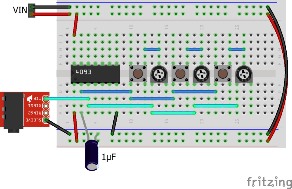
Here is a simple switched version of the previous circuit, with three “keys” and hence three possible notes.
The schematic for the above is as follows:
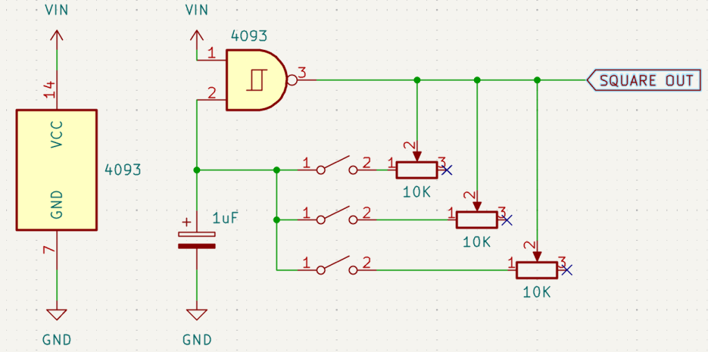
This makes it a little easier to see what is going on. Essentially we have three different resistor values available, but which one gets connected to the circuit is dependent on one of the switches being pressed.
In principle there could be as many switches and potentiometers as we like. And this is essentially the principle behind the Oskitone Poly555 except that is using a 555 timer circuit rather than a NAND oscillator, and actually the Oskitone has an individual, tunable, oscillator per key which allows for whole keyboard polyphony.
Note, that if two or more switches are pressed at the same time, then we’ll end up with several resistors in parallel giving a lower total resistance. This means that the resulting note would change as a result. So I guess one could argue that there are more possible notes than just three, but I’m not sure they’d be particularly useful notes…
A Step (or 8) Further
I’m not particularly interested in building a circuit with lots of switches on a breadboard, but some of the other circuits in the book have planted some interesting ideas.
Later on in the book, a few other chips are added to the mix:
- CD4017: Decade Counter
- CD4040: 12-Stage Ripple-Carry Binary Counter/Divider
- CD4046: Phase Locked Loop
- CD4051: 8:1 way Analog Multiplexer
- CD4053: 3-channel Analog Multiplexer
- CD4066: Quad Bilateral Switch
I won’t spoil the fun here (buy the book, I’m not linked to it – I bought my own copy, but it really is good), but it has really paved the way for me to reconsider how to use logic chips with oscillators.
What I’m interested in now is using the CD4051 analog multiplexer in place of the switches of the previous circuit, allowing me to “address” a note to be played by the oscillator.
The CD4051 datasheet has this diagram showing how it works:
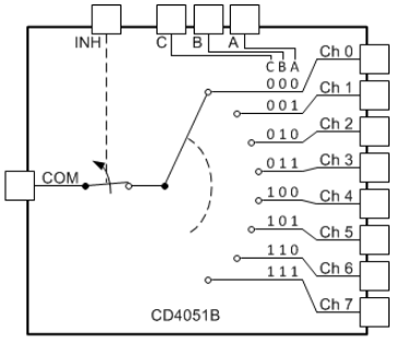
This allows one of 8 circuits to be made, depending on the values of ABC, which are binary coded through the 8 values from 000 (0) to 111 (7).
The book pairs this with a CD4040 to count through the 8 values and hence produces a 8-step pitch sequencer from three chips, 8 pots, and a few passive components. But I want to drive the three address lines in a different way.
For now I’m going to connect each one up to each of the spare NAND oscillators – the 4093 has four NAND gates in total. The idea is that each of the bits will be controlled by a different oscillator, so as they go on and off in various combinations I’ll get what might feel like a fairly random selection between 0 and 7, and thus a fairly random note. I’m hoping for some interesting combinations as the they count in and out of phase.
But at this point I’m not even going to attempt to wire this up on a breadboard, so I’ve gone ahead and had a PCB built.
PCB Design
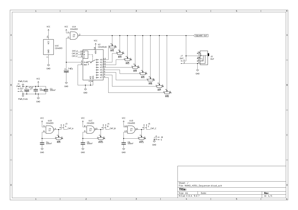
In the design I’ve included a jumper between each controlling oscillator and the sequencer, which allows the possibility of something externally controlling the sequence. I’ve also included two GND connections for use too.
I’ve also included jumper headers for power in and (audio) signal out. Note: the output signal is a 0-5V square wave signal and it is wired to the tip and shield of a TRS socket. The ring is left unconnected so either a mono or stereo lead can be used.
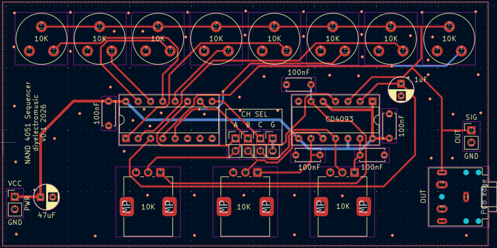
There are one or two silkscreen erratas on this board:
- I managed to miss out the label for the 4051, but as I’ve put it in the name for the PCB, I’m guessing that can probably be figured out in the future, when I’ve forgotten why I designed this board…
- I perhaps should have labelled the pots and trim pots.
- As described below, the values for the components used for the three additional oscillators are more useful if changed.
It might have been more useful to allow the channel select jumpers to be directly jumpered to GND, allowing me to test each oscillator in isolation, by grounding the other two channel inputs. But that can be done with leads.
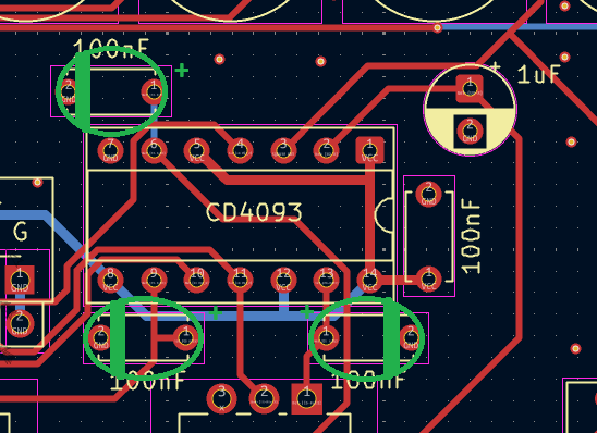
So, with hindsight, there is something I should have changed on this design. The three oscillators as described are generating audio frequencies, but to drive the sequences I really want them to be acting as low-frequency oscillators. To do this, the capacitors should be swapped from 100nF to something more like 22uF, and the pots are better as 100K pots.
Unfortunately this doesn’t fit so well on the PCB – well the capacitors don’t anyway. The following highlights where the capacitors should be placed, and their polarity, instead. But it should be doable.
Bill of Materials:
- PCB
- 1x 4051 8:1 way Analog Multiplexer
- 1x 4093 quad NAND
- 8x 10K trimpots
- 3x 100K PCB mount potentiometers
- 2x 100nF ceramic capacitors
- 1x 1uF; 3x 22uF; 1x 47uF electrolytic capacitors
- 1x 3.5mm PCB mount stereo TRS socket
- Jumpers and header pins
- 1x 14-way; 1x 16-way DIP sockets
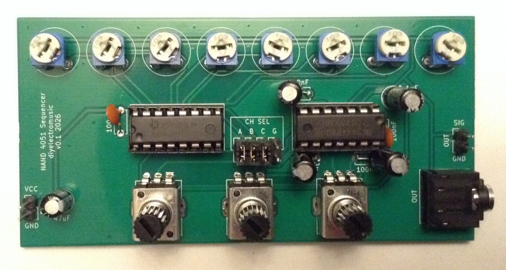
Here is a photo of a finished build:
Closing Thoughts
This was a really nice diversion. I do like the idea of using digital signals from something to select notes, so I’ll definitely come back to that at some point.
I’m not entirely sure I have anything of particular musical interest yet. But for now, it has shown some of the principles, and the book has really set off a number of ideas about using logic chips with oscillators. So I’ll come back to that at some point too.
Kevin

Hi Kevin,
I always like to read your posts, because you are experimenting so much.
This one reminds me of the good old times when I was young.
LikeLike
I agree with your feelings about this book – it’s excellent! I read it cover to cover and have been making some of the circuits. I love the way you developed the idea and made a board.
LikeLike
@diyelectromusic.com In addition to being an author, musician, and builder, Kirk is a really good instructor. I'm taking his pedal class right now and just built my first Schmidt Oscillator.
Kirk and his business partner Sean Holloway have offered remote workshops for builders since COVID and they're something special. After signing up, they send you a box of electronic components, meet as a group weekly via Zoom, and work through that week's activities.
Their classes are approachable and satisfying for anyone interested in making their own gear. Students have included musicians, builders, hackers, and simple enthusiasts like myself. Unfortunately they're getting out of the remote workshop game, so once this year's classes wrap up, that's it.
Their DIY Synth class show you how the components of a synth work and how to hook them together. DIY Rhythm Widgets focuses specially on drum synth basics. Anyone who enjoyed the book will love the class.
LikeLiked by 1 person
Remote Reply
Original Comment URL
Your Profile
Why do I need to enter my profile?
This site is part of the ⁂ open social web, a network of interconnected social platforms (like Mastodon, Pixelfed, Friendica, and others). Unlike centralized social media, your account lives on a platform of your choice, and you can interact with people across different platforms.
By entering your profile, we can send you to your account where you can complete this action.