Having spent a bit of time attempting (although I’m not sure I’m succeeding yet) to understand how to get a useful filter for my Pico Touch Board Audio, I thought it would be useful to have a simple template PCB that could be used for a range of PWM low-pass filtering options.
This is my design.

Warning! I strongly recommend using old or second hand equipment for your experiments. I am not responsible for any damage to expensive instruments!
If you are new to electronics and microcontrollers, see the Getting Started pages.
The Circuit
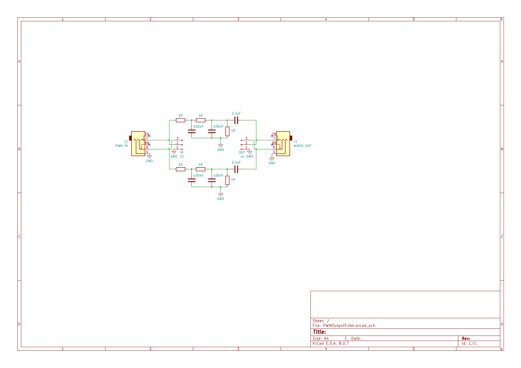
This is following on from the discussion in Pico Touch Board Audio creating the template for a simple two-stage low-pass filter with an option for including a potential divider resistor to drop the overall voltage too.
I’ve doubled the circuit to allow for stereo in and out if required and have included both 3.5mm TRS sockets and pin jumper headers for both input and output.
It requires no power, being a completely passive filter.
If stereo is not required, then just one of the circuits can be populated – ideally the one connected to the TRS tip.
PCB Design

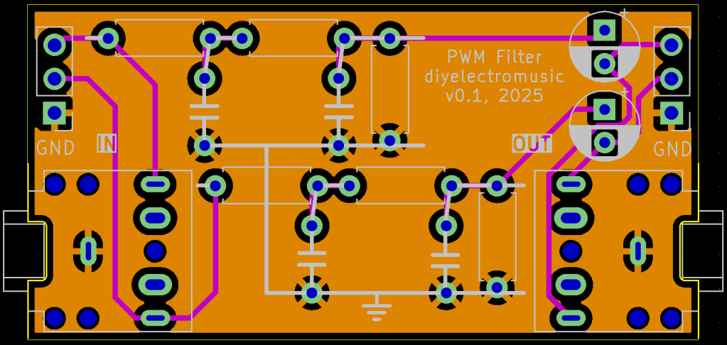
There isn’t much to this pcb layout really. I was particularly keen to keep the PCB away from specific values of components, so instead used the silkscreen to present a pseudo-circuit diagram to make it clear which components are which.
I’ve also tried to leave enough room for the electrolytic capacitors to allow them to be bent over if required.
Closing Thoughts
With hindsight, I can think of a couple of additions that would have been useful on the silkscreen – labelling which circuit is left and right for example.
And having the boards back, I should have added manual “wavy line” resistor diagrams rather than rectangles, but it is enough for what I need.
And it might have been useful to include some additional test points for connecting an oscilloscope.
Kevin
