A while back I tried to use several SSD1306 displays with an Arduino (see OLED MIDI Display – Part 2) and got into trouble with memory. I have another need for multiple displays coming up, so thought I’d revisit the idea to see what could be done.
This shows use to use several cheap SPI-based displays together with an Arduino.
Warning! I strongly recommend using old or second hand equipment for your experiments. I am not responsible for any damage to expensive instruments!
These are the key Arduino tutorials for the main concepts used in this project:
- Adafruit Mini TFT 0.96″ 160×80
- Adafruit ST7735 GFX Library
- https://emalliab.wordpress.com/2025/07/19/small-microcontroller-displays/
If you are new to Arduino, see the Getting Started pages.
Parts list
- Arduino Uno.
- 2x 0.96″ ST7735 60×180 SPI TFT displays.
- Breadboard and jumper wires.
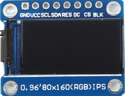
I’m using displays that look like this – note the order of the pins.
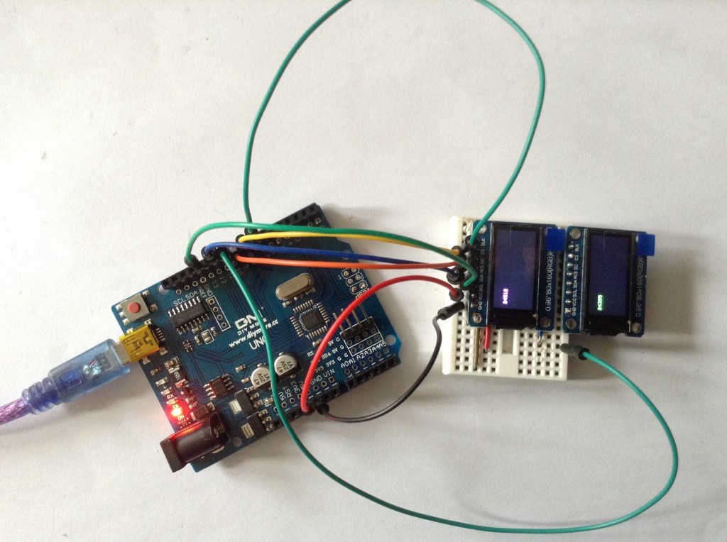
The Circuit

The display pins are connected to the Uno as follows:
| BLK | N/C | Backlight control – not required |
| CS | D10/D7 | Chip select – one for each display. |
| DC | D8 | Data/Command |
| RES | D9 | Reset |
| SDA | D11 | Data (MOSI) |
| SCL | D13 | Clock (SCLK) |
| VCC | 5V | Power |
| GND | GND | Ground |
Notes:
- I’m using the Arduino Uno’s hardware SPI peripheral so the use of D11/D13 is fixed and can’t be changed.
- All signals apart from CS are shared between both boards.
- However – need to ensure that the boards are only reset once!
The Code
There are several software libraries that could be used for these kinds of displays. I’m using the Adafruit libraries:
- Adafruit_GFX
- Adafruit_ST7735_Library
These aren’t always ideal for generic no-name displays as they are geared up to support Adafruit products directly.
A case in point: there is no generic initialisation for a ST7735 display, but rather a number of bespoke initialisations that relate to Adafruit’s range of displays only. I was looking for some means of setting the display size (160×80) but that isn’t possible.
But as it happens, there are two initalisation options that map onto the above boards:
#include <Adafruit_GFX.h>    // Core graphics library
#include <Adafruit_ST7735.h> // Hardware-specific library for ST7735
#include <SPI.h>

#define TFT_CS1       10
#define TFT_CS2        7
#define TFT_RST        9
#define TFT_DC         8

//#define TFT_TYPE INITR_MINI160x80
#define TFT_TYPE INITR_MINI160x80_PLUGIN   // Inverted display

Adafruit_ST7735 tft1 = Adafruit_ST7735(TFT_CS1, TFT_DC, TFT_RST);
Adafruit_ST7735 tft2 = Adafruit_ST7735(TFT_CS2, TFT_DC, -1);

void setup() {
  tft1.initR(TFT_TYPE);
  tft2.initR(TFT_TYPE);
}
Notes for this initialisation code:
- The use of pins D11 and D13 for SPI is assumed, and RST and DC are common.
- I’m using the “INITR_MINI160x80_PLUGIN” initialisation option which is the same as “INITR_MINI160x80” but with the colours inverted. Without this, the built-in colour options aren’t correct for my boards.
- Notice how in the second initialisation I’m using “-1” as the RESET pin so that the first display isn’t reset again after being initialised.
- Both instances have their own CS pin defined.
- The resolution and display size is fixed at 160×80.
In my case I also used setRotation(3) to rotate the displays by 180 degrees.
Here is my complete test code that prints the current millis() count to each display in a different colour.
#include <Adafruit_GFX.h>    // Core graphics library
#include <Adafruit_ST7735.h> // Hardware-specific library for ST7735
#include <SPI.h>

#define TFT_CS1       10
#define TFT_CS2        7
#define TFT_RST        9
#define TFT_DC         8

//#define TFT_TYPE INITR_MINI160x80
#define TFT_TYPE INITR_MINI160x80_PLUGIN   // Inverted display

Adafruit_ST7735 tft1 = Adafruit_ST7735(TFT_CS1, TFT_DC, TFT_RST);
Adafruit_ST7735 tft2 = Adafruit_ST7735(TFT_CS2, TFT_DC, -1);

void setup() {
  tft1.initR(TFT_TYPE);
  tft2.initR(TFT_TYPE);
  tft1.setRotation(3);
  tft1.fillScreen(ST77XX_BLACK);
  tft2.setRotation(3);
  tft2.fillScreen(ST77XX_BLACK);
}

void loop() {
  unsigned long time = millis();
  tft1.fillRect(10, 20, tft1.width(), 20, ST77XX_BLACK);
  tft1.setTextColor(ST77XX_GREEN);
  tft1.setCursor(10, 20);
  tft1.print(time, DEC);
  delay(100);

  time = millis();
  tft2.fillRect(10, 20, tft2.width(), 20, ST77XX_BLACK);
  tft2.setTextColor(ST77XX_MAGENTA);
  tft2.setCursor(10, 20);
  tft2.print(time, DEC);
  delay(400);
}
Closing Thoughts
This is a really good start. What I’d like to do is see how far I can push it, see how many displays it is possible to hook up, and what the overheads of updating them might be.
Then depending on where that leaves me, I can have a think about if I need an alternative microcontroller, like a RP2040 or ESP32 – something with several cores might be particularly useful for this – and see how things go.
Then I can start to think about the musical uses I have in mind.
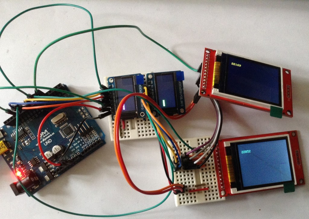
Update: It seems to work with four displays too. I’ve attached two 1.8″ ST7735 displays just to try it (these are “INITR_18BLACKTAB” displays). See photo below!
Kevin