This a version of the ESP32 WROOM Mozzi Experimenter PCB for the latest ESP32-S3 DevKitC board I’ve found.
For the background on the boards themselves, see my notes here: ESP32 S3 DevKit.
Warning! I strongly recommend using old or second hand equipment for your experiments. I am not responsible for any damage to expensive instruments!
If you are new to Microcontrollers, see the Getting Started pages.
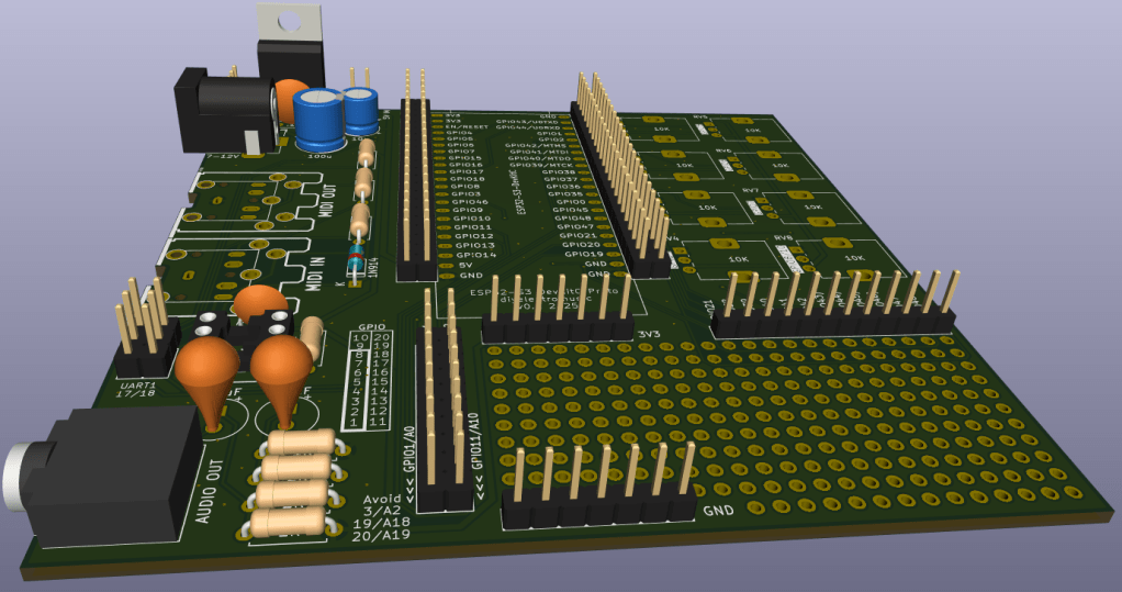
The Circuit
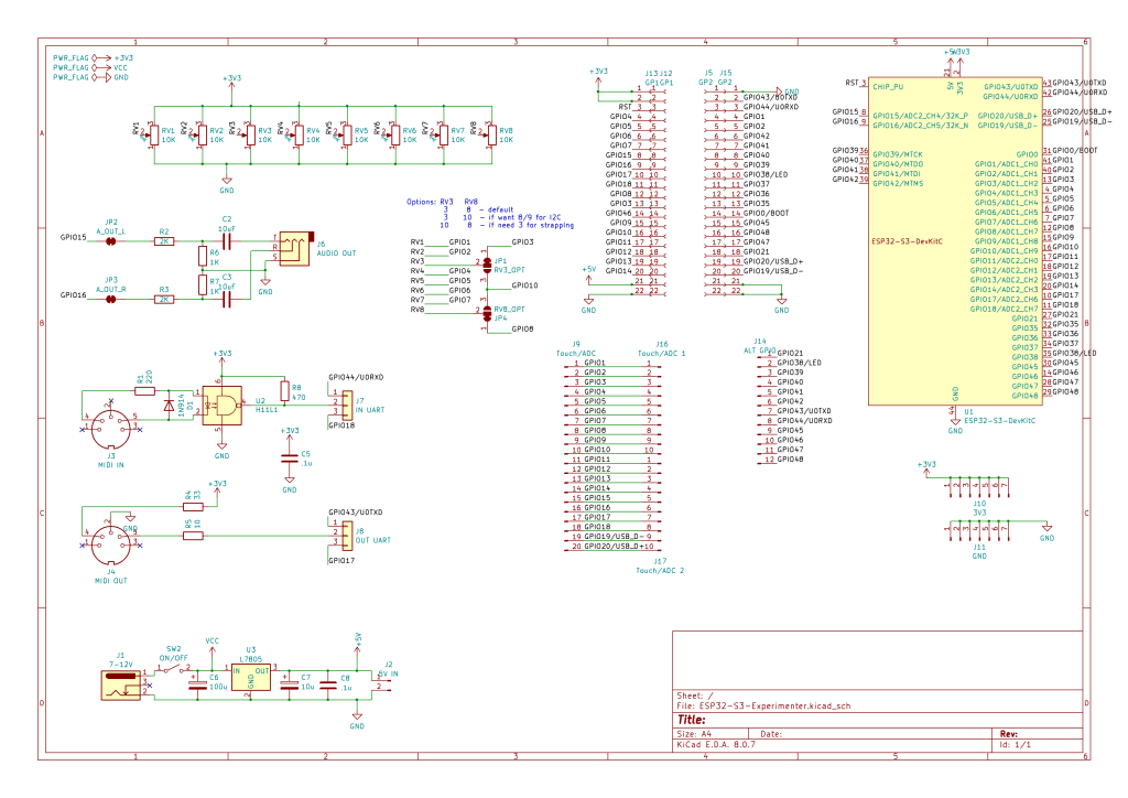
This is mostly just breaking out the pins of the ESP32S3 DevKitC to header pins, but there are a couple of additional features too:
- There are additional rows of headers. The idea is to support the official and clone boards, which means coping with the fact the clone boards are 1 row of pins wider than the official boards.
- There is MIDI IN and OUT with jumpers to select UART0 or UART1.
- There is a stereo PWM output circuit (see notes below).
- There are 8 potentiometers connected to ADC1.
- There is a 7805 or equivalent regulator to provide power if required.
One slight complication is the possibility that GPIO3 (ADC1_CH2) is required as a STRAPPING pin or that GPIO8 (ADC1_CH7) is required for I2C (more in the previous post) so there is a solder bridge option for either of them to switch over to GPIO10 (ADC1_CH9) instead.
The complete GPIO usage is as follows:
| GPIO0 | On board BOOT button |
| GPIO 1-8 | Potentiometer 1-8 |
| GPIO 10 | Optional replacement for GPIO 3 or 8 |
| GPIO 15, 16 | PWM audio output |
| GPIO 43, 44 | MIDI if UART0 is selected |
| GPIO 17, 18 | MIDI if UART1 is selected |
| GPIO 1-20 | Analog breakout area* |
| GPIO 21, 38-49 | Digital breakout area* |
| GPIO 38 or 48 | Onboard RGB LED |
* As already mentioned some of these have alternative or preferred functions.
Audio PWM Output
I based this on the output circuit for my ESP32 WROOM Mozzi Experimenter PCB Design, but I was forgetting that the original ESP32 has a DAC and so only requires a potential divider to reduce the voltage levels and a capacitor to remove the DC bias.
The ESP32S3 does not have a DAC, so the output will have to be via PWM if no external DAC is added. This means this output circuit really needs a low-pass filter to smooth out the pulses from the PWM signal.
That hasn’t been included in the design, but can be implemented by adding capacitors across the terminals of the 1K resistors, as shown below.
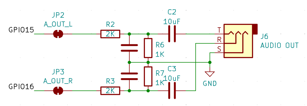
Following the discussion from Arduino PWM Output Filter Circuit, we can see that a 2K/1K potential divider can (loosely) be treated as a ~666K resistor for the purposes of a low-pass filter calculation. So this gives me various options in terms of capacitor size as follows.
| Resistor | Capacitor | Roll-off frequency |
| 666K | 10nF | 24 kHz |
| 666K | 33nF | 7 kHz |
| 666K | 68nF | 3.5 kHz |
| 666K | 100nF | 2.4 kHz |
The greatest smoothing will come with the lowest cut-off, but 2.4kHz or 3.5kHz will limit the higher audio frequencies somewhat. But a 10nF might not give me enough smoothing.
It will also depend somewhat on the PWM frequency chosen. The higher, i.e. above the audio frequency range required, the better.
I’ll start with adding 33nF and see how that looks then might change with some experimentation.
If an external DAC is used, then there are solder jumpers provided that can be broken to disconnect this part of the circuit anyway.
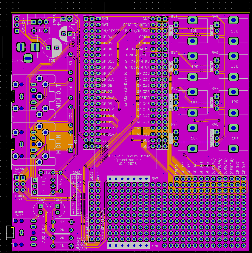
PCB Design

I initially considered only breaking out GPIO pins that weren’t being used for additional functions, but then decided I’d just break them all out alongside the prototyping area. Any pins that might be problematic or have an existing function on the board are labelled in brackets – e.g. (GPIO 43).
The solder jumpers for the GPIO/ADC choices are on the underside of the board.
As previously mentioned, the headers are arranged such that it will support the official DevKitC or the slightly wider clones.
The jumper for UART selection for MIDI can serve as a “disable MIDI to allow use of the serial port” function too if required.
There is also a twin jumper option for direct 5V input instead of going via the barrel jack and regulator.
Closing Thoughts
The omission of the capacitors in the PWM filter is a small annoyance, but it is relatively easily fixed.
Apart from that, there is a fair bit included on this board. It should serve as a good platform for further experimentation.
Kevin
