I’ve been having a conversation on discord helping someone to try to work out the keyboard matrix of a keyboard in order to eventually use it with a microcontroller.
But discord being discord, its fine for chat, but we’re both starting to lose track of where we’re at in the analysis, so I thought I’d write up what we have so far to refer back to. And it might help someone else attempting to do the same thing.
Warning! I strongly recommend using old or second hand equipment for your experiments. I am not responsible for any damage to expensive instruments!
If you are new to Arduino, see the Getting Started pages.
Previous Projects using a Keyboard Matrix
These are some of my previous projects that have tried to work out or implement a keyboard matrix.
- Keyboard MIDI Matrix Decode
- Toy Keyboard Matrix Decode with the Pi Pico
- Toy Keyboard Tone Piano – Part 5
- Yet Another Toy Keyboard USB MIDI Controller – Part 2
The Principle of Operation of a Keyboard Matrix
There are some great resources out there describing how a keyboard matrix works. Here is a really good one describing lots of options:
But the general idea is that it isn’t possible to have one switch with its own IO pin, so a 2 dimensional matrix is created with some shared GPIO pins serving many keys, but they can only be activated by a common GPIO pin.
Typically the number of keys supported is thus number of shared pins x number of common pins.
The pseudo code for scanning them will go something like this:
Set all COMMON pins as OUTPUTs
Set all KEY pins as INPUTs with PULLUPs

Set all COMMON pins HIGH
FOREACH COMMON pin:
  Set that COMMON pin LOW:
    FOREACH KEY pin:
      IF KEY Pin is LOW:
        The key at location COMMON+KEY has been pressed
  Set COMMON pin HIGH again and move onto the next COMMON pin
By going through this loop quickly enough, a microcontroller can scan an entire keyboard pretty efficiently.
So, in general we will need COMMON + KEY number of IO pins to serve COMMON x KEY number of keys.
There are various additional tricks that can be used to reduce the number of IO pins even further – using things like shift registers, multiplexers, line decoders, or IO expanders. These trade number of IO pins for additional chips and code complexity.
One issue to watch out for with a keyboard matrix is the concept of ghosting. I talk through the issue in this post: Pi Pico MIDI Matrix Decode – Part 4.
The general problem is that with a matrix arrangement, having two keys pressed at once can create spurious paths through the matrix making it appear that a key has been pressed when it hasn’t.
The way to solve that is to use diodes as part of the matrix to ensure that the current can only flow in the expected direction and not via odd paths when several keys are pressed at the same time.
You can read more about the issue and how to solve it here:
The Problem
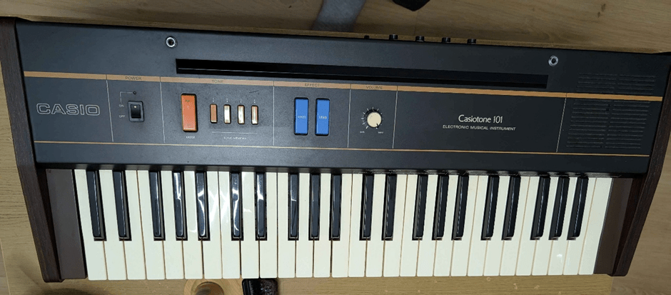
In this specific case, we were attempting to work out how the keyboard matrix for a Casiotone CT-101.
So my main reference for working out the matrix of an old keyboard is: Keyboard Matrix Decode so those are the principles I’ll be following here.
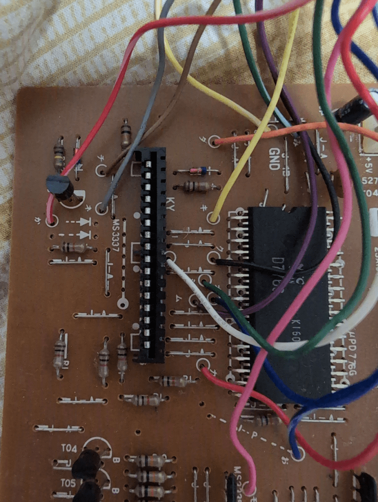
Here is a photo of the main PCB keyboard connector:
And the reverse:
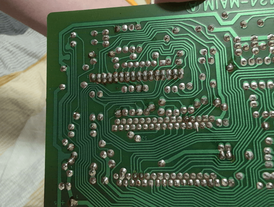
So my initial thinking is that the larger traces around the edge might be power and GND, but if this is a pure matrix then there won’t be any power or GND links on that connector – it might be all matrix.
Those parallel connectors on the unpopulated/unconnected set of holes might be a clue – maybe that is one side of the matrix?
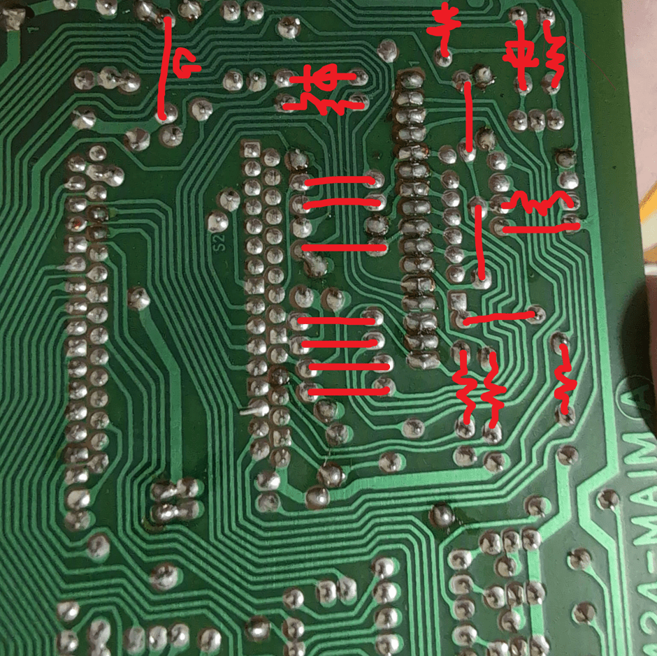
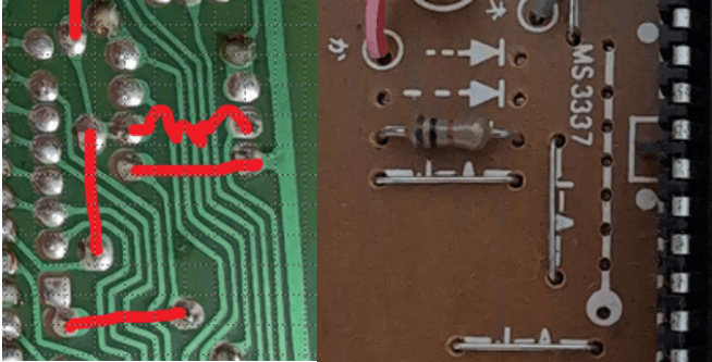
Here is an annotated version of the above, completing some of the links from the other side of the PCB:
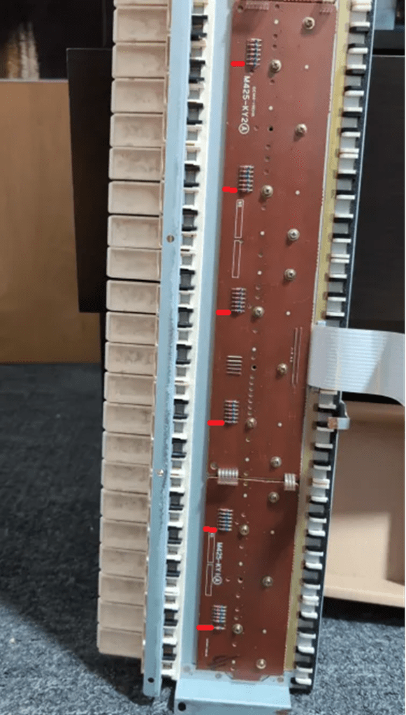
At this point, we switched to the keyboard PCB itself.
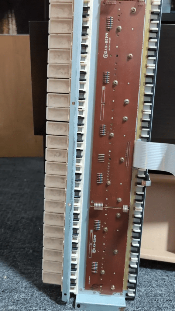
There are a number of clues here that are really helpful.
So we can see blocks of six diodes, which will be there to stop ghosting. That is a good place to start. Each bank of six implies a pattern to me – so I wonder if there are six lines on one side of the matrix. It would be worth trying to work out which diodes connect to which wires in the ribbon – that might give one set of common points.
There are 49 keys, so a 6+8 matrix would give 48, so it might need 6+9 to fully scan the whole thing.
interesting – its a 16 way connector and I’m not sure, but it looks like the connection near the “1” isn’t connected to anything making 15 = 6 + 9…
I’d guess at this point that those spare 7 holes alongside the connector on the PCB might be test points for the 6 common parts of the matrix – it looks like the bottom one might be connected to GND.
It looks like the 3rd one down isn’t connected – it goes to that unfilled link/arrow/(diode?). So I initially wondered if that might be for bigger keyboards that need 7 common links. But then I realised that it is connected on the other side of the board to a black/white wire.
At this point, my suggestion is to focus on the keyboard PCB. We need to map out the diodes to the ribbon with a meter then try to link LEDs between those ribbon links and the rest to see if we can work out which keys are linked to which pairs of the ribbon.
At this point I’d guess that we’ll find each of the bottom (say) diodes share a common link on the ribbon – so that should be a quick test.
In fact this backs that up too – looks like 6 common points shared between the PCBs and 3 additional links to cover the number of keys – 3×6 means up to 18 off this additional PCB…
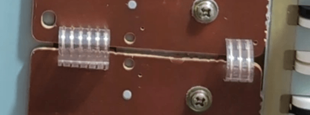
That smaller PCB might be serving 13 keys – 2×6 plus one extra hence needing three COMMON lines.
At this point I’m thinking that the six wires connect to every 1 in 6 keys each. Then which set of 6 keys is governed by the other links – but without testing with a meter/LEDs I’m just guessing – it could be the other way round 🙂
Taking out the small pcb might reveal the pattern…
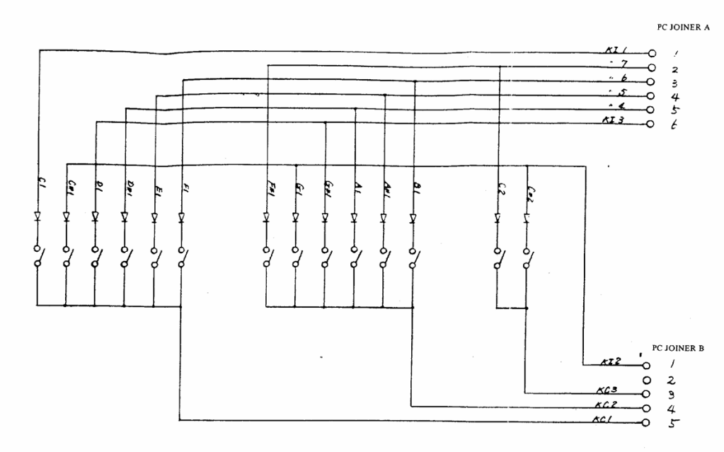
At this point I went off in search of anything that might help. Then I found this in a Casio CZ-5000 service manual: … this is PCB M425-KY3 – the CT-101 PCB is labelled M425-KY1.
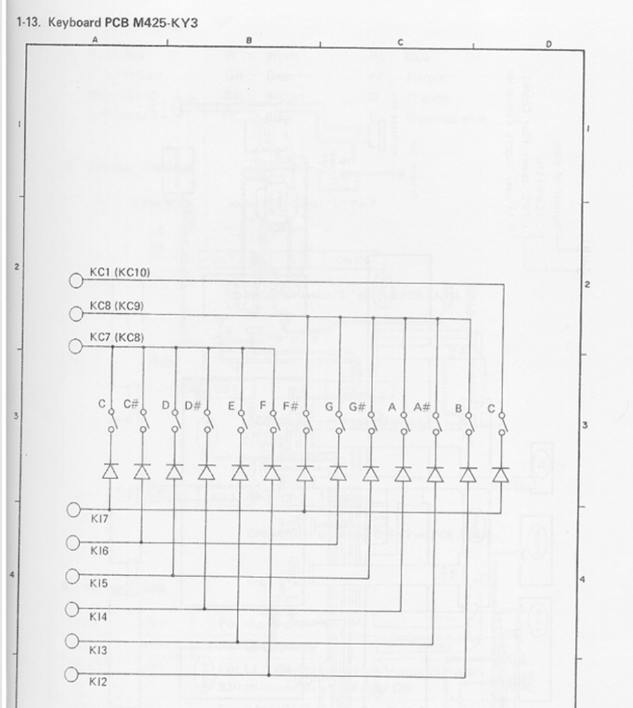
That looks very, very similar to how that small PCB might work – notice the 6 KI lines and 3 KC lines, serving 13 keys.
From the same manual, I found this:
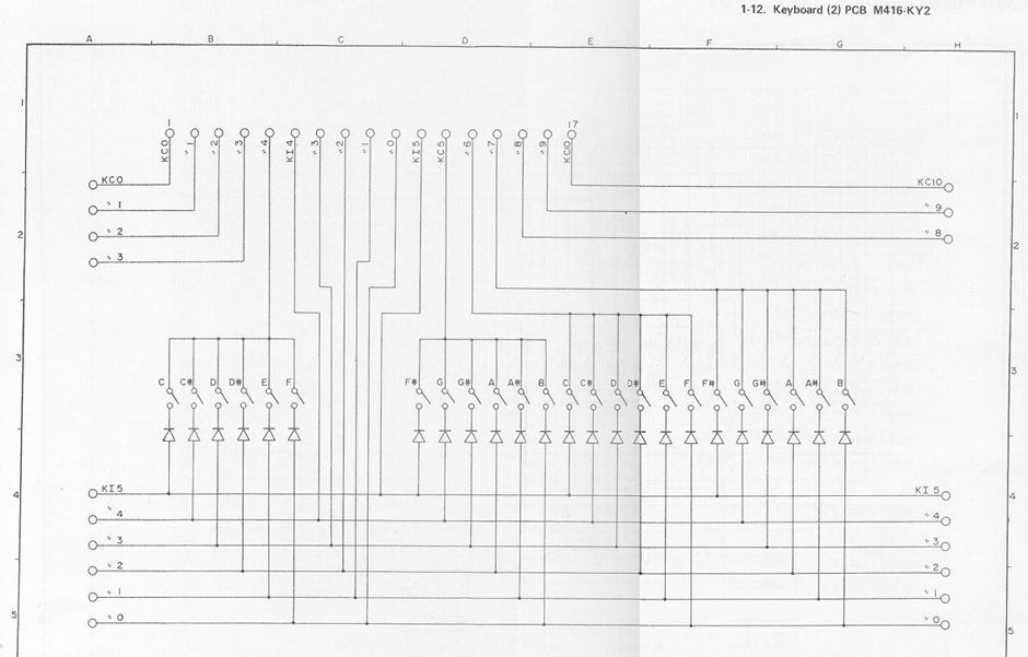
So at this point I’m wondering if the same mapping might have been used with the ribbon on the CT-101 too.
It ought to be possible to stick an LED between say KI7 and KC5 and see which key makes it work. If these schematics apply I think that would be the top key…
I think at this point I’d be probing that ribbon with a meter/LEDs to see if it matches this schematic and if so – we have the matrix.
I think our chances are pretty good that the centre of the ribbon is those 6/7 test points I mentioned earlier on the other PCB.
In fact at this point I’m pretty sure this would match – the topmost pin doesn’t look connected – that would be KC0 on the CZ5000 which has 61 keys so will need the additional line…
Actually there are 17 pins on the CZ-5000 – there are 6 common pins for both, but the CZ needs two extras to add another octave on (2×6 = 12).
So I think for the CT-101 there are 6 “data” lines at the bottom, then 6 common lines, then 3 more “data” lines at the top, and then one spare, unconnected. This is shown below.
When testing, it has to be remembered that the keyboard has some diodes too – so it is important to make sure the LED/power go the right way round to work with the diodes on the PCB too.
At this point, we managed to find a service manual for a Casiotone CT-401 which was really handy! Here are some useful extracts.
PCB M422-KY1:
PCB M422-KY2:
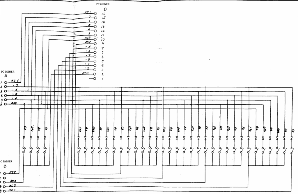
The keyboard matrix:
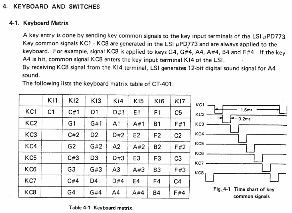
Section 4.1 of that manual gives a hint at what they might have done with the CT-101. The trick is working out which are the KC lines and which are the KI lines.
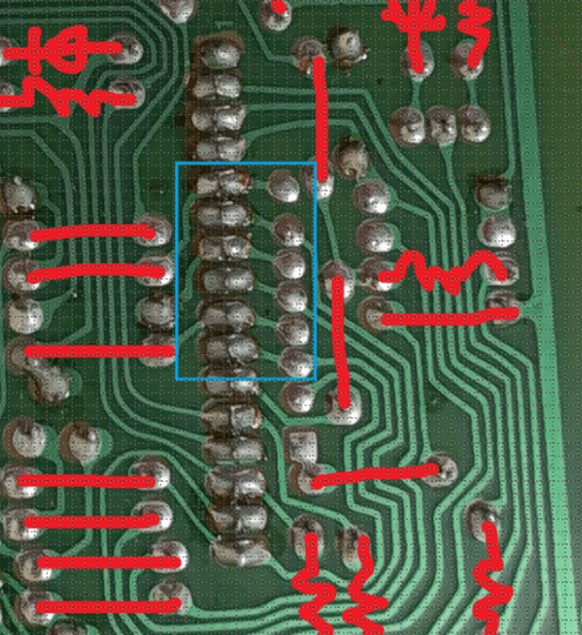
It should be possible to buzz-out for continuity from one side of those diodes to the right connections on the ribbon and that should at least give an idea of where the 6 KI lines are. Looking back at that schematic – the non-line side of the diodes should be connected to each other and one KI line – I’ve highlighted KI0 below as an example:

I’m guessing the leads of the diodes I’ve highlighted in the photo below would be connected together and then all of them to one of the ribbon connections.
If we can repeat that for each of the six diodes that will give us the 6 KEY lines for the matrix (KI).
Once the six KI lines are mapped out, we can then use a circuit a bit like this one to work out where the different KC connections are:
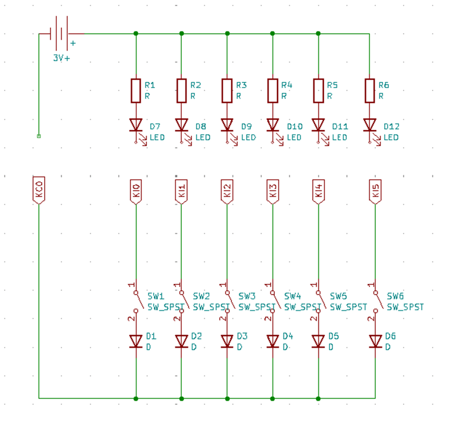
i.e find out which keys in each octave use KC0; then move the battery connection to KC1 and repeat; then KC2; etc and the slowly map out which of the keys correspond to which of the KC and KI lines.
The aim is to be able to label the ribbon with KI and KC numbers and then make a table like the one in section 4.1 of the service manual.
Note – I almost always get the direction wrong in a matrix the first time I think about it. It isn’t helping that the CZ circuit I found is shown the opposite way round to the circuit in the CT service manual! But I think the KI lines should be the positive side of the battery and the LEDs aligned accordingly.
Eventually we’ll have an experiment going something like:
- Connect to KC0
- Work out which keys are now connected to KI0 to KI5
- Then connect to KC1 and do the same for KI0 to KI5
Then eventually we’ll get something like:
- C2 = KC1 + KI4
- C2# = KC1 + KI5
- D = KC2 + KI0
- D# = KC2 + KI1
and so on.
Closing Thoughts
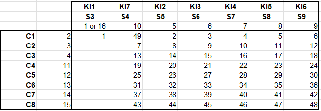
We believe the matrix looks as follows:
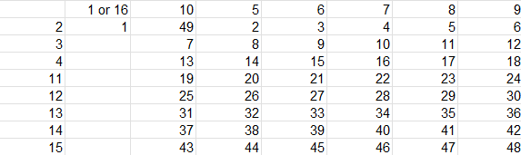
Where the pin numbers across the top and down the left hand side are the pin numbers from the ribbon cable. The numbers in the table go from 1 to 49 and correspond to the keys themselves, from left (lowest C=1) to right (highest C=49).
There are a few oddities – like why is pin 10 apparently the lowest note of each set of six… apart from the first set, where it seems to be note 49? And why do pins 1 or 16 seem to be connected to give the first not?
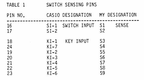
More recently, I’ve found the “Casio Mod Guide” by Robin Whittle, which has a description of the key matrix for some similar boards. It states:
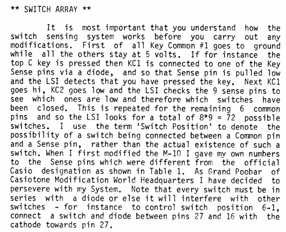
I don’t quite know if this maps over onto the CT 101 or not, but probably need to sit and unpick those sentences and the provided tables to see!
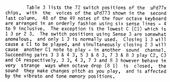
Some more clues:
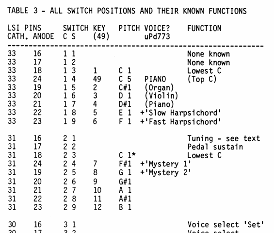
Combining these tables with the pins from the experimental mapping gives me the following:
So that does seem to match with the oddities in the mapping. I’d say with that, we have the full list of KIn and KCn mappings now.
Hopefully this gives a bit of insight into the kind of process required to do this kind of thing. Do let me know if you manage to save and repurpose a keyboard!
Kevin
