Here are the build notes for my Waveshare Zero MIDI Proto PCB Design.

Warning! I strongly recommend using old or second hand equipment for your experiments. I am not responsible for any damage to expensive instruments!
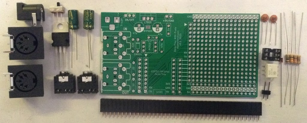
Bill of Materials
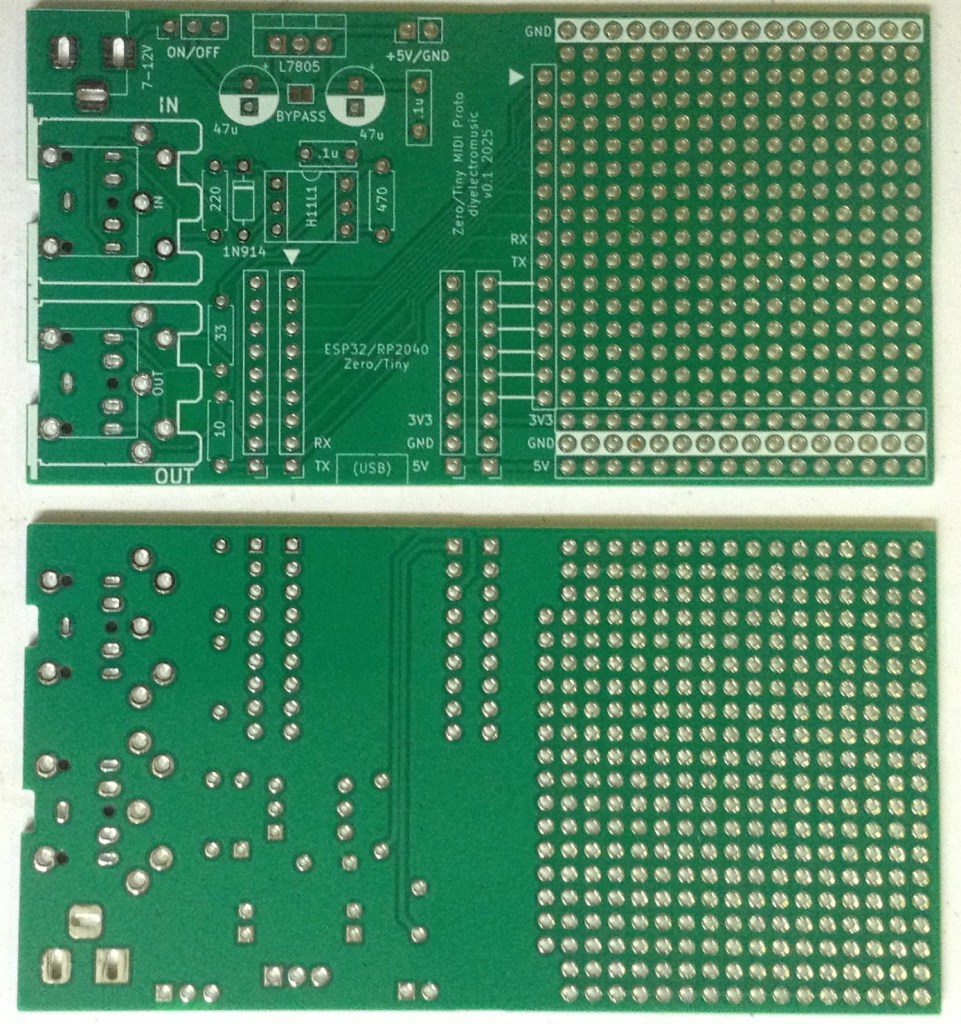
- Waveshare Zero MIDI Proto PCB (GitHub link below)
- 1x H11L1 optoisolator
- 1x 1N4148 or 1N914 signal diode
- 1x 10Ω, 1x 33Ω, 1×220Ω, 1×470Ω resistors
- 1x 100nF ceramic capacitor
- 2x 5-pin MIDI DIN sockets OR 2x TRS MIDI sockets
- Optional: 1x 6-way DIP socket
- Optional: 2x 9-way pin header sockets
Power supply
- 1x 7805 regulator (optional)
- 1x 100nF ceramic capacitor
- 2x 47uF electrolytic capacitors
- 1x 2.1mm barrel jack
- 1x SPST 3-pin, 2.54mm pitch, switch
- 2-way pin header
Build Steps
Taking a typical “low to high” soldering approach, this is the suggested order of assembly:
- All resistors and diode.
- DIP socket (if used) and TRS sockets (if used).
- Disc capacitors.
- Power switch.
- 2-way pin header.
- 9-way pin socket headers.
- Electrolytic capacitors.
- Barrel jack.
- DIN sockets (if used).
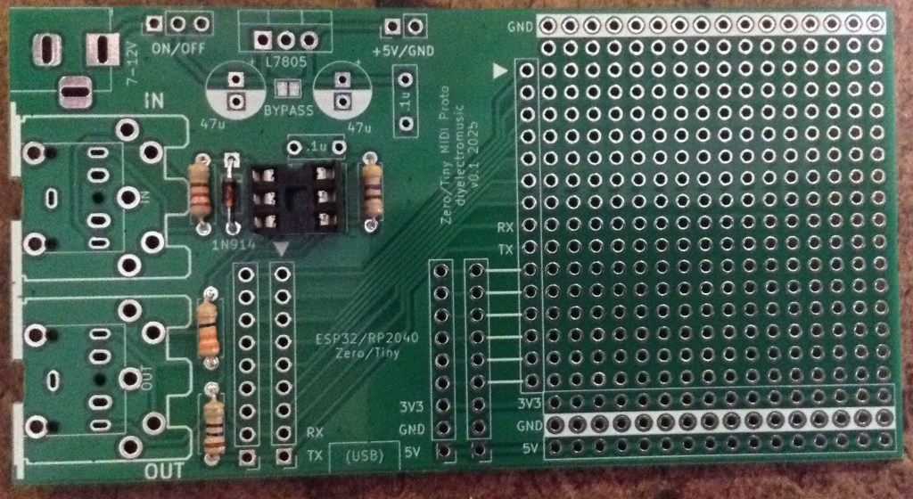
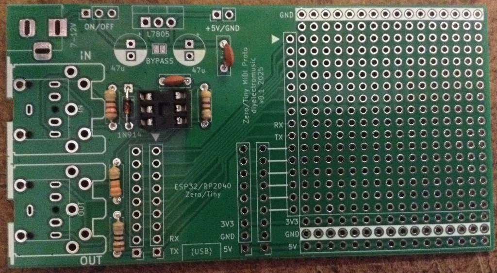
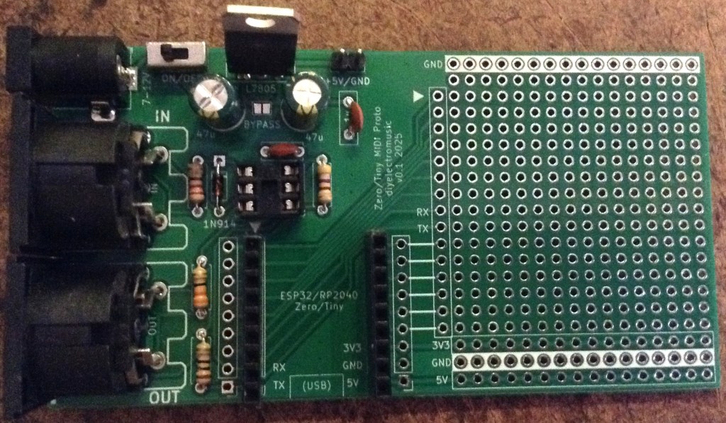
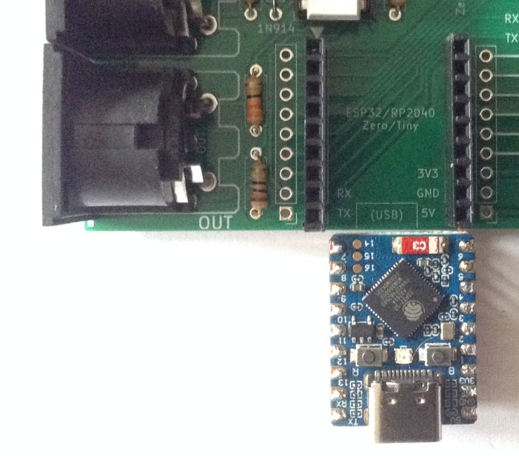
Here are some build photos.
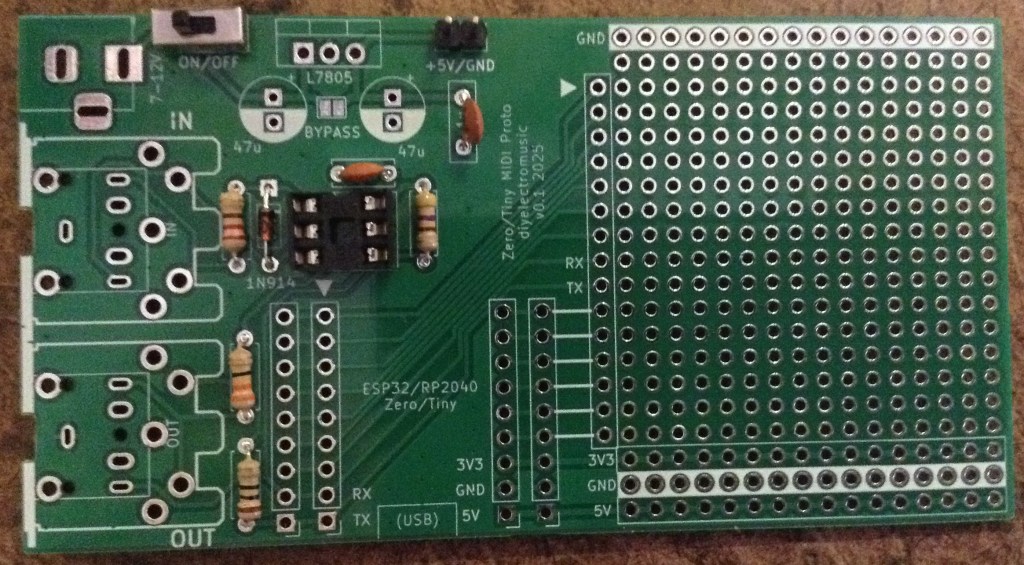
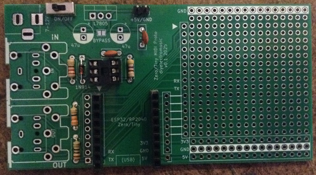
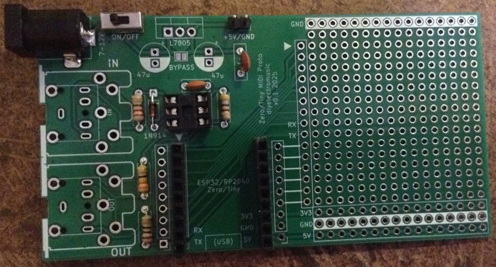
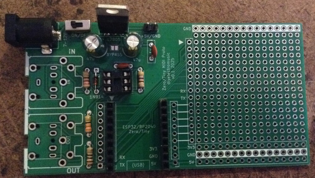
V1 Errata
Note: the first version of the board (in fact the one used in the above photos) has two errors:
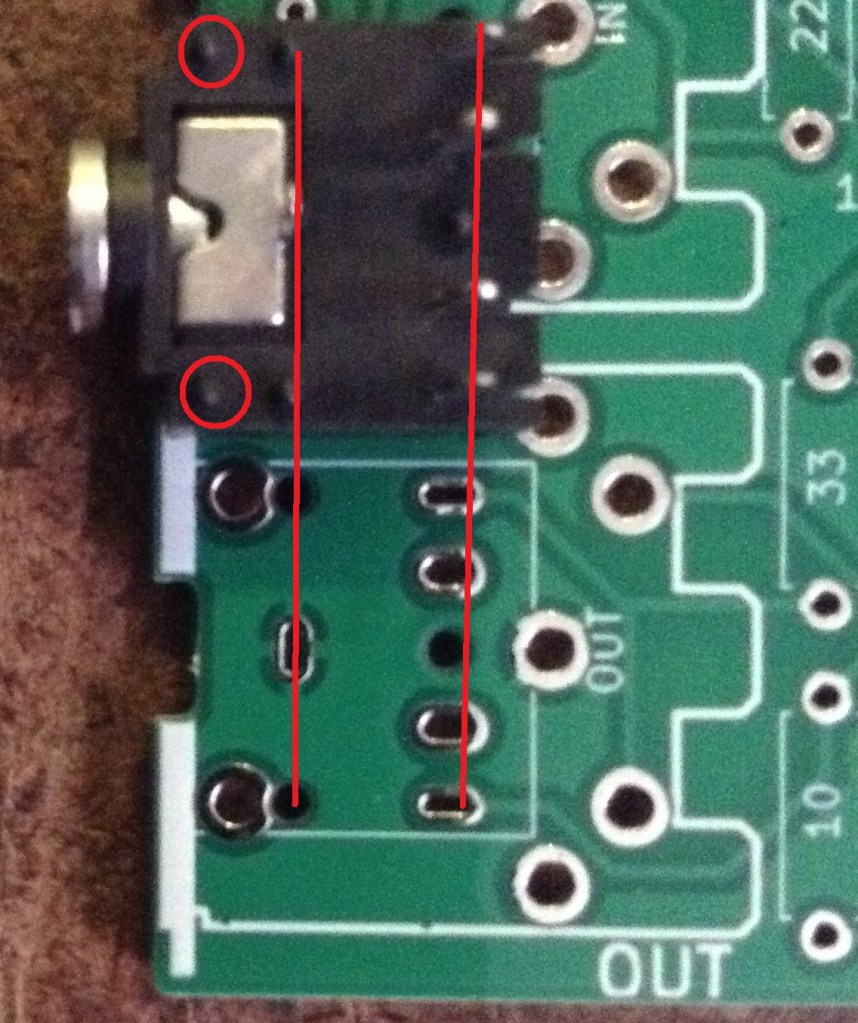
The footprint of the TRS socket doesn’t quite line up properly with the MIDI DIN socket. The TRS sockets can still be used, but the outer plastic alignment pins need to be removed as they don’t align with the holes, as shown below.
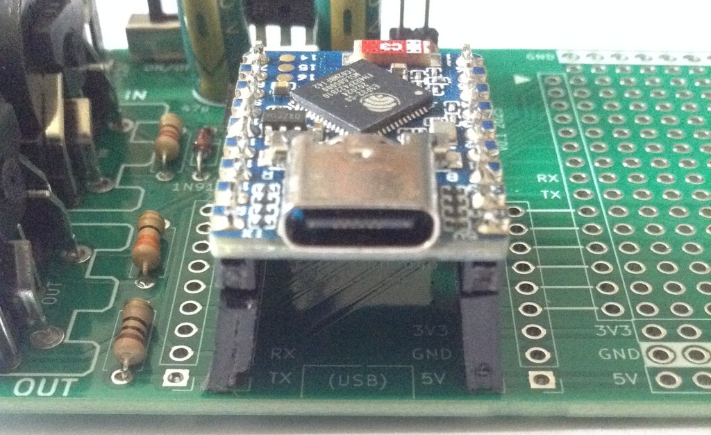
The more serious error in the first version though is that the spacing of the headers for the Waveshare Zero is 2.54mm too wide.
Curiously, they do fit the board used in my ESP32C3 OLED Mini MIDI Montor, but RX/TX are not in the right place for this board.
If tall headers (he usual, cheaper ones) are used then they can be slightly bent enough to get a board fitted, but this isn’t ideal.
Both of these issues have been fixed in the version stored on GitHub.
Testing
I recommend performing the general tests described here: PCBs.
PCB Errata
As already mentioned, there were some issues with V1 of the PCB, but at the time of writing there are no further issues with the version on GitHub.
Enhancements:
- None.
In Use
The board can be powered in one of four ways:
- Using the USB-C connection of the Waveshare Zero.
- Using 7-12V input via the barrel jack.
- Using 5V directly via the 2-way pin header.
- Using 5V input via the barrel jack provided: the regulator is not populated and the bypass solder bridge is connected.
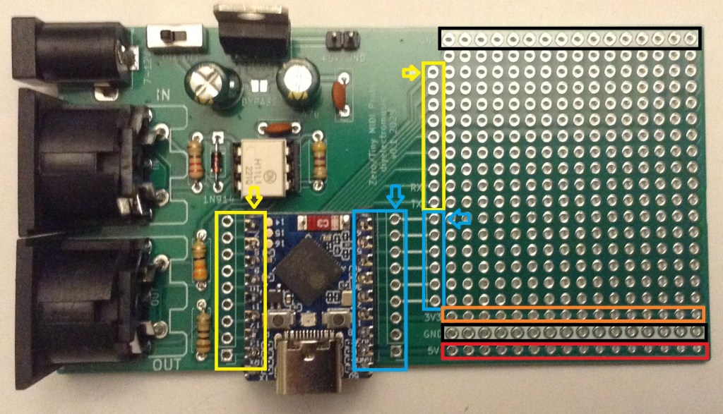
The two rows of pins from the Waveshare Zero are duplicated and broken out to headers near the prototyping area as shown below. There are also rows of 5V, 3V3, and two rows of GND.
Arduino Support
Both the ESP32-S3 and ESP32-C3 will use the ESP32 Arduino Core from Espressif, available here: https://github.com/espressif/arduino-esp32
For my two Waveshare Zero boards I’ve used the following board settings:
- Waveshare ESP32-S3-Zero
- ESP32C3 Dev Module
For the RP2040 Zero and Tiny2040 I’ve used the unofficial RP2040 Arduino core from here: https://github.com/earlephilhower/arduino-pico
And there are board settings for both of the boards directly:
- Pimoroni Tiny2040
- Waveshare RP2040 Zero
MIDI Serial Port Usage
For the ESP32-S3 and ESP32-C3, if the ESP32 Arduino Core is used, then the serial port connected to MIDI should be initialised as follows:
// For ESP32-C3
// Do not use MIDI_CREATE_DEFAULT_INSTANCE()
MIDI_CREATE_INSTANCE(HardwareSerial, Serial0, MIDI);

// For ESP32-S3
// Either of these work
MIDI_CREATE_DEFAULT_INSTANCE();
MIDI_CREATE_INSTANCE(HardwareSerial, Serial0, MIDI);
For the RP2040 using the unofficial Arduino Pico core, the serial port connected to MIDI should be initialised as follows:
// Do not use MIDI_CREATE_DEFAULT_INSTANCE()
MIDI_CREATE_INSTANCE(HardwareSerial, Serial1, MIDI);
Closing Thoughts
Those two mistakes were annoying and arguably might have been found if I’d printed out the PCB layout and checked it. Or maybe not.
Anyway, they were fairly easy to sort out and the V1 board is actually quite usable for me anyway.
Kevin
