Here are the build notes for my MiniDexed EuroRack PCB Design.
This is a DIY module only for use in my own DIY system.
Do NOT use this alongside expensive modules in an expensive rack. It is highly likely to cause problems with your power supply and could even damage your other modules.

Warning! I strongly recommend using old or second hand equipment for your experiments. I am not responsible for any damage to expensive instruments!
If you are new to single board computers, see the Getting Started pages.
Bill of Materials

- MiniDexed EuroRack PCB (GitHub link below)
- Front panel
- Raspberry Pi Zero (1 or 2)
- GY-PCM5102 module
- 128×32 SSD1306 OLED display module (pins order: GND-VCC-SCL-SDA)
- 1x L7805 regulator
- 1x H11L1 optoisolator
- 1x 1N5817 Schottky diode
- 1x 1N4148 or 1N914 signal diode
- 1×220Ω, 1×470Ω resistors
- 5x 10nF ceramic capactiors
- 3x 100nF ceramic capacitors
- 2x 47uF electrolytic capacitors (low profile if possible – see text)
- 1x switched rotary encoder with a threaded shroud and nut
- 2x tall tactile buttons – 6x6mm base, at least 12mm height (it needs to poke through the panel!)
- 16-way shrouded EuroRack style power header.
- 40-way GPIO header (optional: extended – see discussion).
- Pin-headers and connecting wires.
Also required: 3.5mm panel mount sockets for audio and MIDI – I use different types, but it will depend on the panel used (see panel discussion).

Build Steps
Taking a typical “low to high” soldering approach, this is the suggested order of assembly:
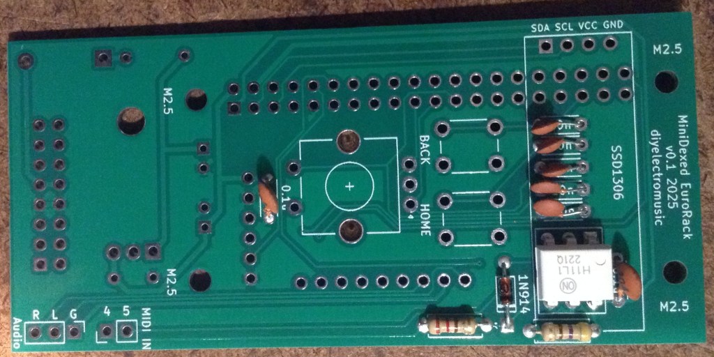
- Resistors and diode on the top.
- H11L1 (assuming soldered directly to the PCB).
- Disc capacitors on the top.
- Diode and disc capacitor on the bottom.
- Electrolytic capacitors on the bottom.
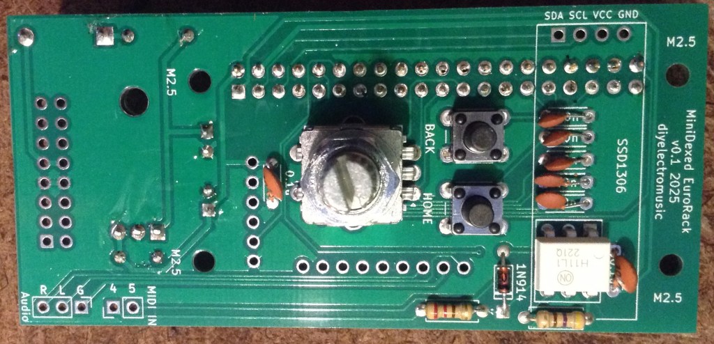
- GPIO and 16-way power socket on the bottom.
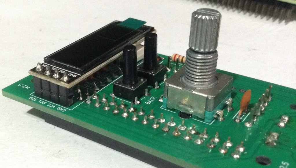
- Buttons and encoder on the top.
- GY-PCM5102 module (see photos for steps required prior to fixing).
- SSD1306 (see photos for steps required prior to fixing).
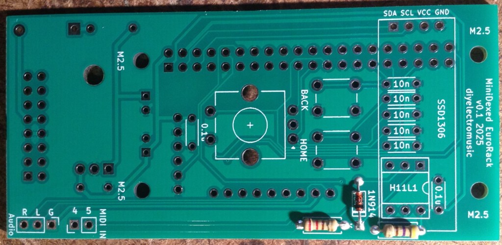
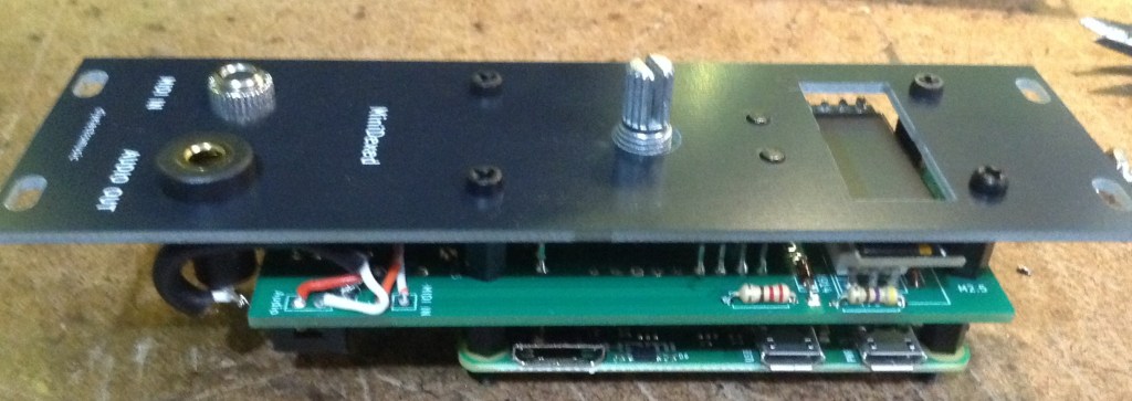
Here are some build photos and more details of the steps involved.
Note: Most of these photos show the build for V0.1 of the PCB. There are some minor updates in V0.2 which will be noted where relevant.
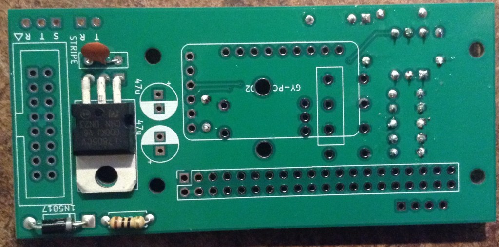
The power circuit on the underside of the board has two options for mounting the regulator. It can go either vertically or horizontally, but with the tab up. Both methods use the same solder holes. Which is chosen will largely depend on what heatsink options there are.

Note: the first version of the board only had a single option, with the tab down, making contact with the PCB. This didn’t really work from a cooling perspective, hence the change.
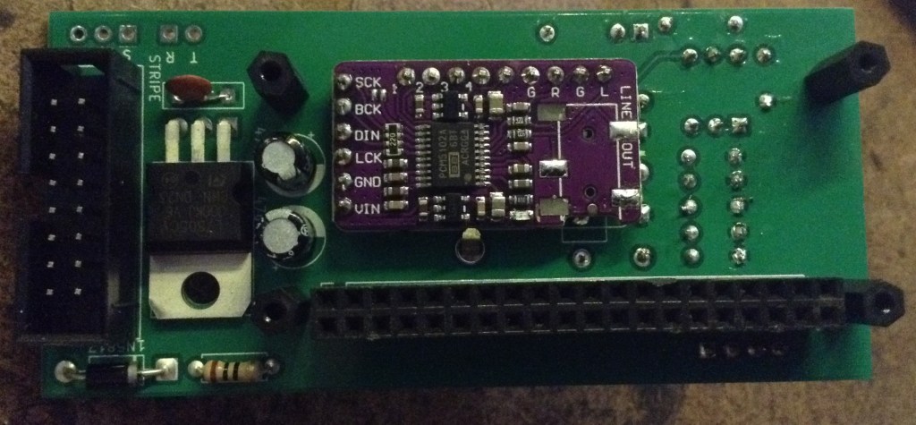
The following “in progress” photos still show the first version of the board with the regulator the other way around, an additional resistor, omitted from V2, and the diode in a different place.
Note that low-profile capacitors may be required as they will sit underneath the Raspberry Pi Zero. If the regulator is “standing up” then it should be possible to bend the capacitors over into the space reserved for the regulator.
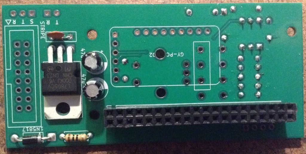

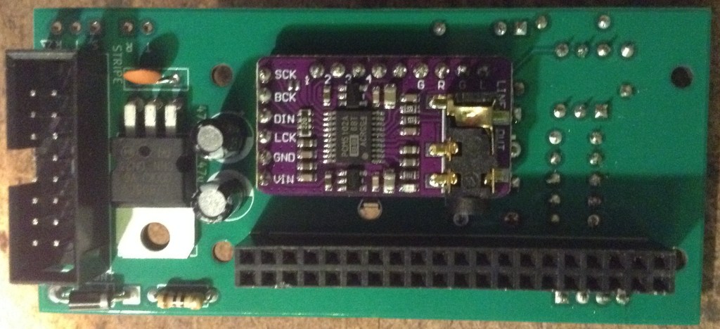
The GPIO headers have to allow enough space for the Zero to be mounted and not interfere with the PCM5102. See discussion below.
The EuroRack headers need to be correctly oriented and shrouded headers are strongly recommended.
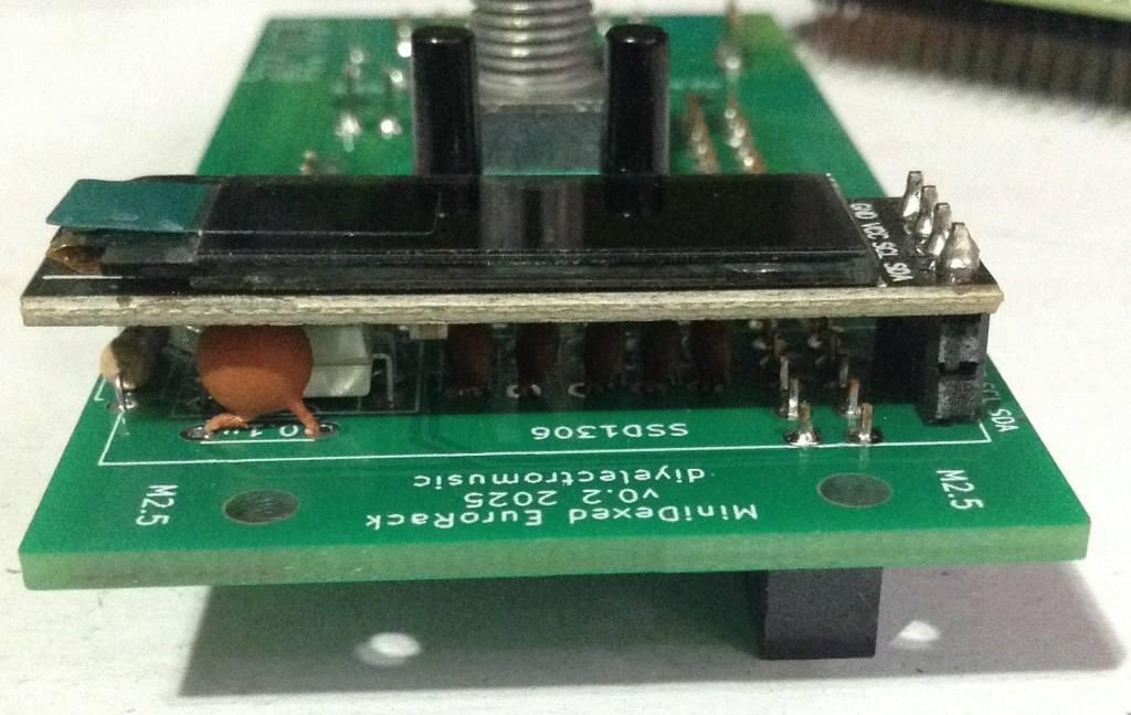
The SSD1306 requires additional spacers on the pins to raise it above the PCB for presentation closer to the front panel.
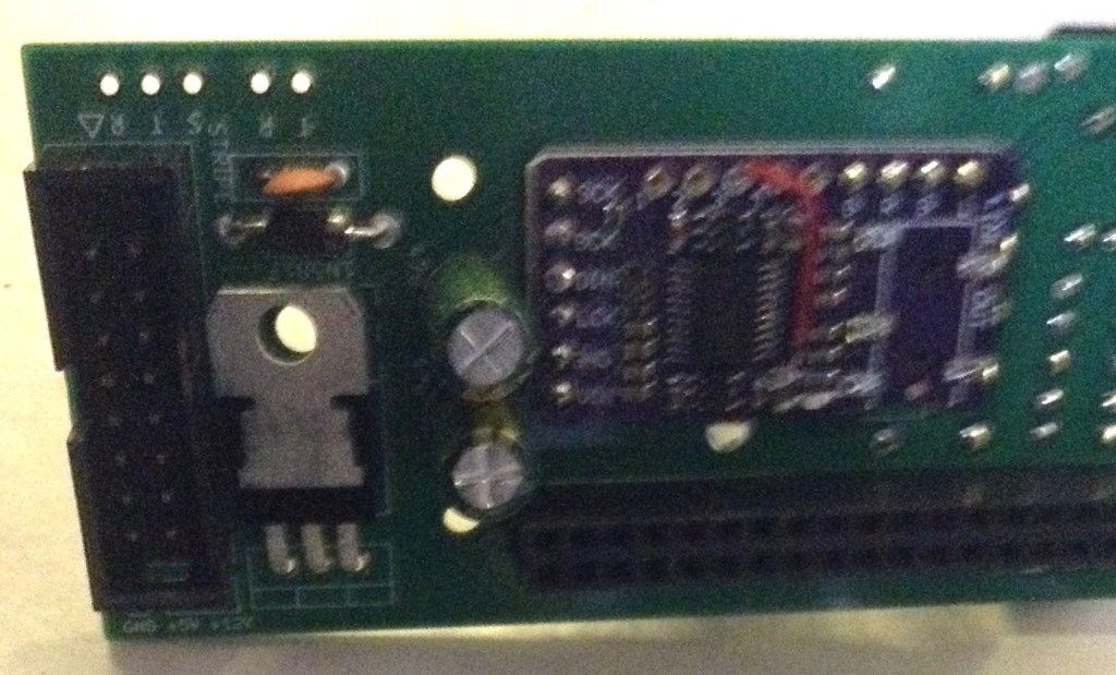
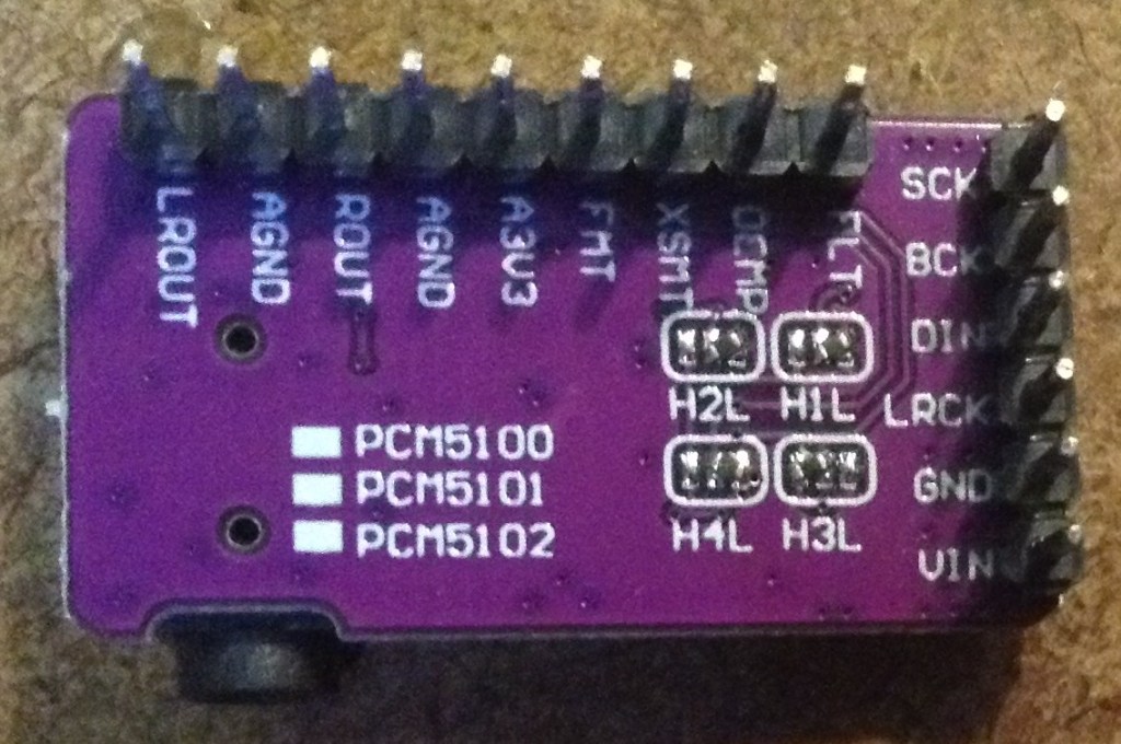
The PCM5102 must have its solder jumpers configured, if not set already, and requires both sets of pin headers adding.
In the photo below, the PCM5102 has zero-ohm, surface mount resistors as jumpers – but it is really hard to see! On first glance, it looks like there is no link configured at all, but they are connected as: 1L, 2L, 3H, 4L.
These modules have to be added after the other components, as they prevent access to the solder pads during assembly.
GPIO Header Options
One option is to use extended headers, which ought to allow room for the Zero and a heatsink (if required) on the main BCM chip. Note: A V2 Pi Zero could probably benefit from a heatsink I’d imagine if running fully processing all 8 tone generators.
Another option is to remove the on-board 3.5mm, SMT, audio jack on the PCM5102 as shown below, and use “normal” sized GPIO headers.
If non-extended GPIO header is used then, as already mentioned, low-profile electrolytic capacitors may be required as they are positioned underneath the Pi Zero too.
Power Options
As previously mentioned, there wasn’t really much choice when it came to mounting the power regulator for V1 of the board, but in V2 I’ve positioned it differently to allow it to be “tab up” or upright.
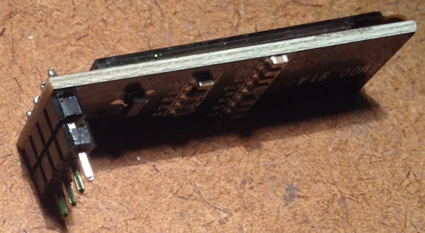
The upright positioning was hopefully placed so that a long, thin heatsink could be mounted alongside the Pi. This shows one of those heatsinks you can get for M2 SSD cards. I figure that drilling a hole in it would do the trick, but I’ve not actually done this myself (see below).

The solution I went with in the end was to actually replace the 7805 with a 7805-compatible DC-DC buck converter. These are available fairly cheaply online.
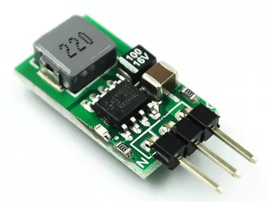
These work a lot more efficiently than a 7805, so especially when drawing 300mA or so from a Pi Zero 2 whilst dropping from 12V down to 5V, they still have no need of a heatsink.
The downside of using these (apparently) is that as a switching power unit, they can be pretty electrically noisy. But as I’m powering a microcontroller rather than a pure analog circuit in the first place, I decided it probably wasn’t going to be making things much worse. This is hardly a high quality, electrically clean build anyway!

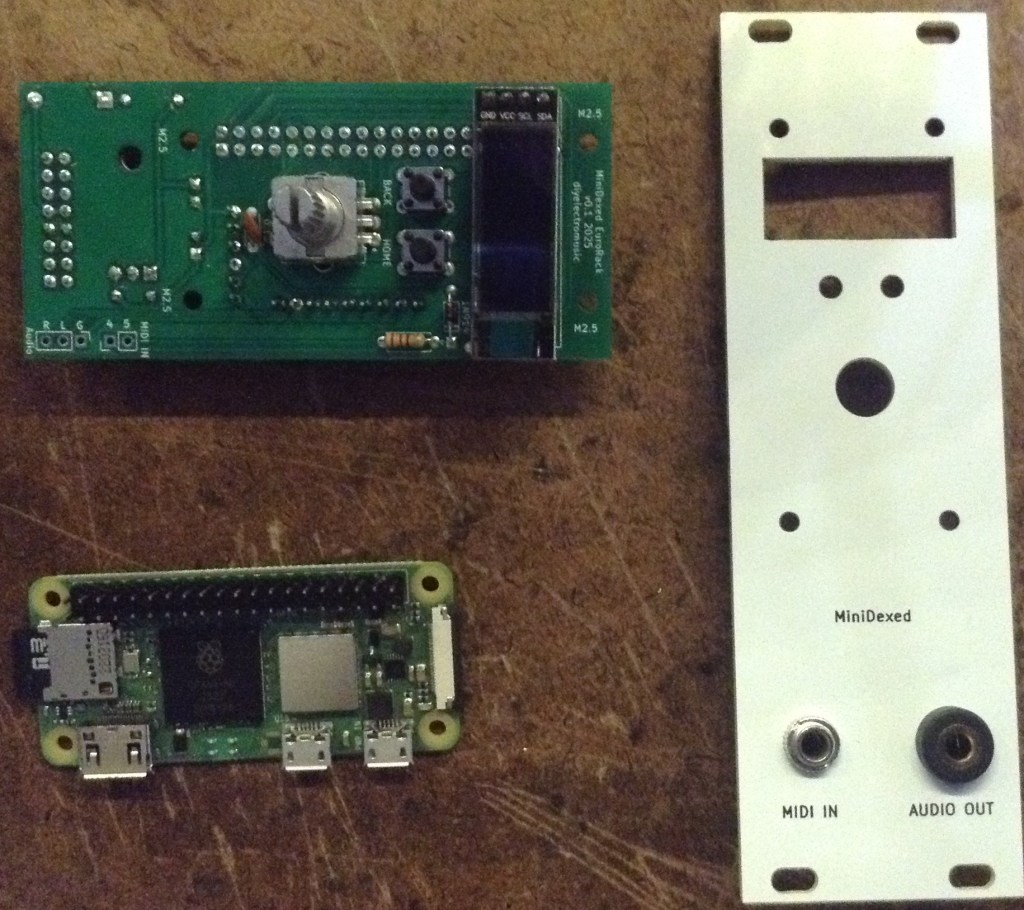
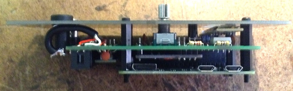
Final Assembly
Required Components to use my panel:
- MiniDexed EuroRack Panel (see Github link below).
- Raspberry Pi Zero (1 or 2) with GPIO header pins.
- MiniDexed EuroRack PCB as described above.
- Panel mount 3.5mm TRS socket for MIDI. 6mm diameter hole assumed.
- Panel mount 3.5mm TRS socket for audio. 8mm diameter hole assumed.
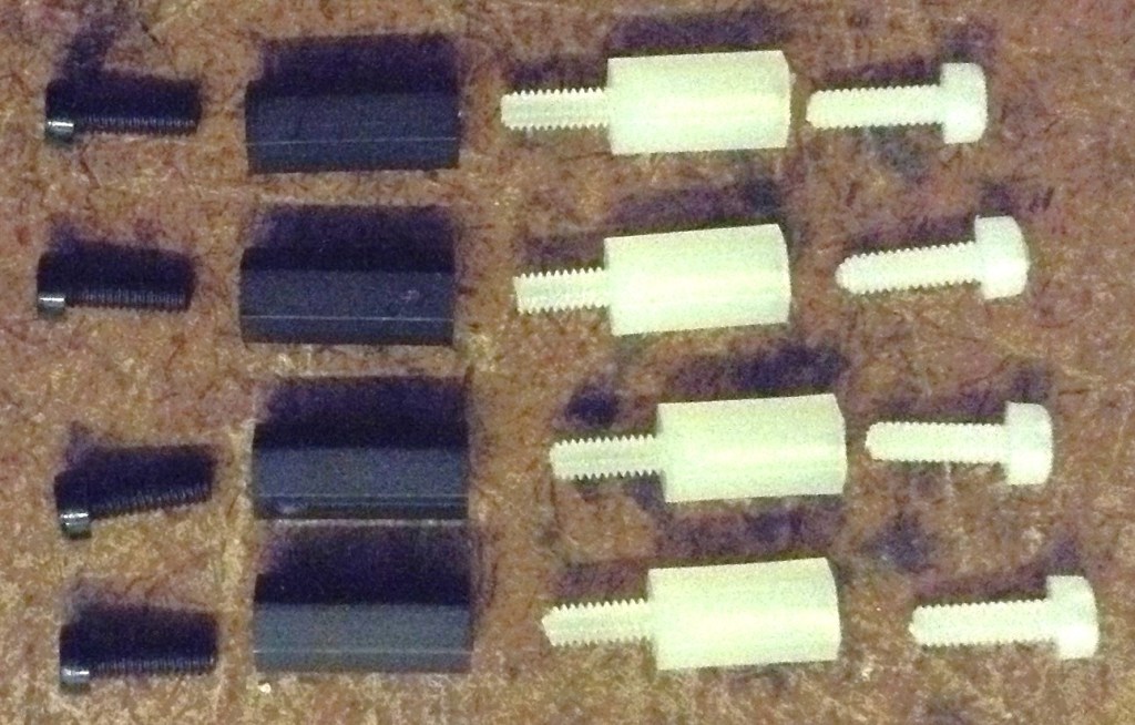
- 2.5mm mounting posts, screws and nuts.
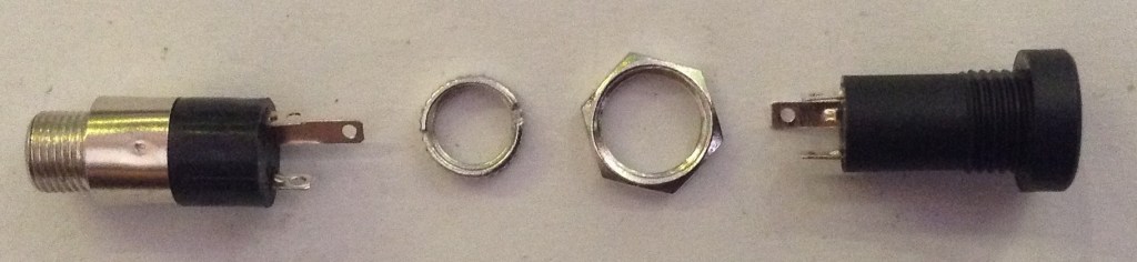
I’m using the same designs of TRS sockets for MIDI and audio that I use in all my modules. These need mounting on the panel. Soldering will come in a moment.
I found that with the GPIO header height I was using, alongside the final height of the SSD1306, height of the buttons, and the encoder’s shroud, that the following mountings were required:
- 2x black nylon 2.5mm 6mm screws
- 2x black 10mm 2.5mm spacers
- 2x white 8mm 2.5mm spacers with screws
- 2x white nylon 2.5mm 6mm screws
An alternative build had a slightly larger gap (due to using 12mm buttons) so required four sets of 10×2.5mm spacers.
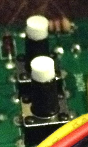
Another quirk of my first build was that I only had 9mm high buttons which wasn’t quite enough to reach through the panel. Ideally a 11mm or larger button would be required.
But this allowed me to 3D print a white 2.8mm diameter, 3.0mm high, extension that I could glue on the top, meaning that the exposed part of the button was white, matching the panel.
My second build used a black panel and 12mm buttons, but as already mentioned this meant the panel had to use 10mm spacers instead of 8mm spacers. One issue with that is that there isn’t much of the encoder shaft exposed. I found some knobs that worked ok, but my preferred (cheap) knobs could not be fitted and still allow the encoder switch to function.
In summary, there is still a fair bit of trial and error with each build depending on the exact combinations of screen height, encoder shaft length, button length and so on.
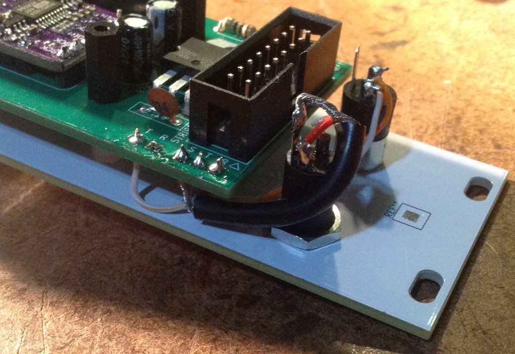
Once the PCB and panel is fixed together then the two 3.5mm sockets can be soldered to the PCB (or connected using headers if that was the preferred option).
Recall that MIDI IN does not required a GND connection. Also double check which solder tabs correspond to the TIP and which to the RING, which should match the “T” and “R” labels on the PCB (“S” is for shield, i.e. GND).

Testing
I recommend performing the general tests described here: PCBs.
Then, prior to plugging in the RPi Zero, do the following:
- Verify that the 12V and GND connections of the EuroRack connector have no shorts.
- Power up the board (no Pi) and verify that there is a 5V signal present and going to the PCM5102 and SSD1306. The PCM5102 should have its red power LED on.
Only then power off, plug in the RPi Zero with an SD card containing MiniDexed (configuration below) and verify that the display, encoder, buttons, MIDI IN, and audio out are all working.
MiniDexed Configuration
The following are the key MiniDexed.ini configuration options required:
SoundDevice=i2s

SSD1306LCDI2CAddress=0x3C
SSD1306LCDWidth=128
SSD1306LCDHeight=32
LCDColumns=20
LCDRows=2

ButtonPinBack=5
ButtonActionBack=click
ButtonPinSelect=11
ButtonActionSelect=click
ButtonPinHome=6
ButtonActionHome=click
ButtonPinShortcut=11

EncoderEnabled=1
EncoderPinClock=10
EncoderPinData=9
PCB Errata
As already noted, there were a number of issues with the first version of the PCB, but these should have been addressed in the published version.
As the time of writing, there are no further known issues with V0.2 of the PCB.
Enhancements:
- I feel like the power situation ought to be better. One option could be to break out a USB connection to the Zero directly allowing the use of a standard “wall wart” type supply.
- Another option might be to make use of the solder pads on the rear of a Zero (like the Zero STEM does).
- It might also be useful to provide a configurable (e.g. solder bridge) link to enable the EuroRack +5V supply as an option.
- There are already options to use internal (within a rack) links for MIDI and audio if required using the pin headers on the PCB, but it might be nice to allow a choice between panel or rear connectors.
Closing Thoughts
I’m still not fully happy with the longer-term implications of how I’m powering these boards, but I’ll see how things go. Those DC-DC converters seem like a feasible option so I’ll see how they perform.
The panel height issue could be better too – it would be nice to have a recommended set of components and a known useful size of spacers, but there is still a fair bit of trial an error at the moment with each build.
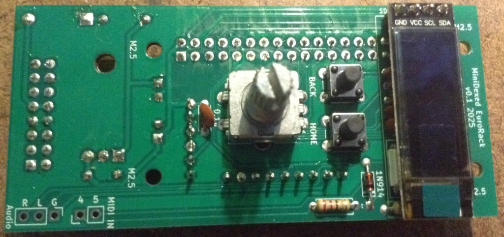
Also, sometimes the display height isn’t perfect, as shown below. I might 3D print a display bezel or surround to help.
The end results looks pretty good though, so for this stage in my thinking about these, I’m pretty pleased with how this has ended up.
But one last time, just to make my position totally clear: this is a DIY system and should only be used with other DIY modules you wouldn’t mind too much losing.
It is NOT for use alongside other commercial (expensive) or treasured modules. There are commercial versions of MiniDexed apparently for that, that I have no experience of.
Kevin


@diyelectromusic.com ok, this is mad 🙂 As you've pointed out, it's way power hungry … We ALL (ducks n runs) are looking forward to your pico version 😉 I was thinking of hacking on that, but, you're much faster than I….
LikeLike
Remote Reply
Original Comment URL
Your Profile
Why do I need to enter my profile?
This site is part of the ⁂ open social web, a network of interconnected social platforms (like Mastodon, Pixelfed, Friendica, and others). Unlike centralized social media, your account lives on a platform of your choice, and you can interact with people across different platforms.
By entering your profile, we can send you to your account where you can complete this action.
@poetaster @diyelectromusic.com I do need to get back to the Pico version. At the very least the RP2350 raises some very interesting possibilities 🙂
LikeLike
Remote Reply
Original Comment URL
Your Profile
Why do I need to enter my profile?
This site is part of the ⁂ open social web, a network of interconnected social platforms (like Mastodon, Pixelfed, Friendica, and others). Unlike centralized social media, your account lives on a platform of your choice, and you can interact with people across different platforms.
By entering your profile, we can send you to your account where you can complete this action.
I should specify that my intention was to go full cv. No midi, just voltages. That would raise the bar on hacking dexed which has held me back.
LikeLike
Remote Reply
Original Comment URL
Your Profile
Why do I need to enter my profile?
This site is part of the ⁂ open social web, a network of interconnected social platforms (like Mastodon, Pixelfed, Friendica, and others). Unlike centralized social media, your account lives on a platform of your choice, and you can interact with people across different platforms.
By entering your profile, we can send you to your account where you can complete this action.
Hi Kevin,
First of all I want to complement your great work. I use some of your design s in my daily routine as a teacher on an Art School. Your PicoTouch MIDI board is now my favourite tool to let the students experiment with microcontrollers, midi, music and sound.
This week I builded your MiniDexd Eurorack module and it works great. So I was wondering if I could rebuild the mt32-pi project but using your hardware pin assignments ( gpio pins used ). I found the place for the definition of the gpio pins in the code but now I have to rebuild/compile it again. But unfortunately the project is no longer maintained and I cannot find any information how to rebuild it from source ( toolchain setup , dependencies..etc.. ) So I was wondering if you have an idea how to do this because you also designed a mt32-pi add-on project before.
Best,
Michel
LikeLike
I’ve not tried to build MT32-Pi myself I’m afraid, but as it is also based on circle, it may be that a fair part of what I say in my post here might also apply to MT32-Pi?
https://diyelectromusic.com/2023/07/21/rebuilding-my-ability-to-build-minidexed/
If I get a chance at somepoint I’ll see what is involved with building MT32-Pi….
That’s great to hear about the Pico touch module! And sounds like you’ve managed to do useful things with MiniDexed too, which is also really cool.
Kevin
LikeLike
Thanks ..that was really helpful. The trick was using an Ubuntu 20.4 LTS in VMware Fusion (I use Mac ).
Everything is working now , so you can post an article where you use your eurorack design now also for mt32-pi 🙂
This is what I did :
Setup a Ubuntu 20.4 LTS system. Works great with VMware Player or Fusion Start a Terminal and do the following package installs
sudo apt-get update
sudo apt-get upgrade
sudo apt-get install build-essential
sudo apt-get install gcc-arm-none-eabi
sudo apt-get install git
sudo apt-get install curl
sudo apt-get install dialog
sudo apt-get install cmake
sudo apt-get install pkg-config
sudo apt-get install glib-2.0 Now clone the mt32-pi github repo
git clone –recursive https://github.com/dwhinham/mt32-pi.git
cd mt32-pi
nano src/control/simpleencoder.cpp In nano change the following lines
constexpr u8 GPIOPinButton1 = 5;
constexpr u8 GPIOPinButton2 = 6;
constexpr u8 GPIOPinEncoderButton = 11;
constexpr u8 GPIOPinEncoderCLK = 10;
constexpr u8 GPIOPinEncoderDAT = 9;
ctrl-X and say ‘Y’
make all
If everything goes well you will have a kernel8.img file in your directory.
Now hook up a microSD cardreader to your Linux environment and insert a blank microSD card
Goto the ~/scripts dir and start mt32pi_installer.sh , this will install all the needed bare metal files
./scripts/mt32pi_installer.sh
When ready copy the kernel8.img file to the SD card
Change in the mt32-pi.cfg file the line ‘encoder_reversed = off’ to on , now the volume knob will increase when turned clockwise
Copy the MT32 roms to to the rom dir
Copy some Sf2 soundfont files tot the soundfont dir
Thats it…unmount the sd card , put it in your Zero 2 W…and boot it.. the MT32pi logo should appear on the oled screen and the buttons and rotary encoder should work properly
The first button switches between m32 and soundfont mode.
The second button will switch to the next rom or soundfont file
The rotary encoder will change the master volume.
The encoder switch only displays a message that the button is pressed
LikeLike
That’s brilliant! Can I add your comments to a note about how to use my design for MT32-Pi?
I’ll have to give that a go now 🙂
Kevin
LikeLike
Yes of course !
And please double check my steps 😉
I am now looking into the menu code..Would be nice to change the sounds of a part / channel like you can do in MiniDexed…but have to dig into it
LikeLiked by 1 person
Instructions worked a treat. The only omission was having to run the installer script as root. I’ve added all the notes here: https://diyelectromusic.com/2025/04/07/mt32-pi-on-my-eurorack-minidexed-pcb/
I’ve also added some of the additional configuration options – things like using the alternate MIDI configuration for the MT32-Pi which I prefer.
Many thanks again! Do keep me up to date with what else you get up to 🙂
Kevin
LikeLike