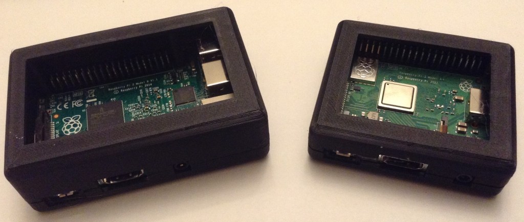
As a prelude to building a case for some of my MiniDexed synth PCBs I was looking for a good starting point for a Raspberry Pi 3D printed case. I’ve found two, but neither was quite what I wanted, so I took inspiration from the two I found and created my own.
This will go on to hopefully allow me to create some synth cases. Watch this space!
Warning! I strongly recommend using old or second hand equipment for your experiments. I am not responsible for any damage to expensive instruments!
If you are new to music and microcontrollers, see the Getting Started pages.
Introduction and Inspiration
There are lots of designs out there for 3D printed Raspberry Pi cases, but I was after something I could use as a basis for my own design and I like to use OpenSCAD, which limits my options somewhat.
But I did find the following designs that use OpenSCAD, and that I liked the look of, online:
- Raspberry Pi 4B Parametric OpenSCAD Case.
- Algot Runeman’s Raspberry Pi Case.
- 3D Printed Raspberry Pi2 Case Designed in OpenScad.
But I really wanted something I could tailor to a Pi 3 or 4 and in the A+ and B+ form factors. Eventually I might want a Zero and V1 too, but those would do for now.
So I used the following ideas:
- The parameterisation approach, and the use of “hull” for the main box, from the RPi 2 case;
- Some of the measurements from the PI 2 and Pi 4 cases;
- The use of intersection() to split the case into two, from the Pi 4 case;
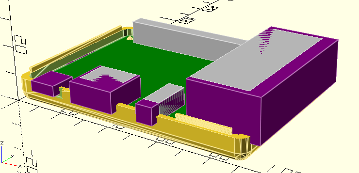
- The idea of including a simplified mock-up of the board from the Pi 4 case;
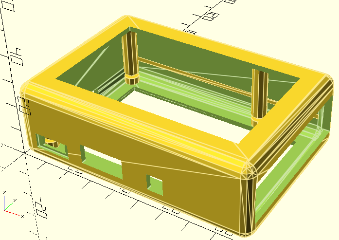
- The design of the case “lips” and stand-offs/clamps from the Pi 4 case;
And so set about designing my own.
OpenSCAD Design
Most of the dimensions required for the Raspberry Pi boards can be found in “Schematics and Mechanical Drawings” section of the Raspberry Pi Hardware Documentation site: https://www.raspberrypi.com/documentation/computers/raspberry-pi.html#schematics-and-mechanical-drawings
The basic idea is as follows:
- Define the dimensions of the board.
- Define the padding around the board and the required thickness of the case.
- Combining the above will give the exterior and interior dimensions of the main box.
- Use hull and spheres to create the basic box shape.
- Use intersection to split the case in two.
- Define a location and dimensions of each peripheral and connector required to be exposed from the board. These are used to create the mock-up board.
- Define a means to extend and alter the location and dimensions of each peripheral. These are used to define the cut-outs in the case for each peripheral.
Here is an example of the structure that defines each peripheral:
gpio  =[[7.2,50.0,0.0],[50.0,5.1,9.0],[0.0,0.0,0.0],[0.0,0.0,0.0]];
ethusb=[[65.5,2.0,0.0],[21.2,52.0,16.0],[0.0,-2.0,0.0],[5.0,4.0,0.0]];
micro =[[6.5,-1.5,0.0],[8.0,6.0,3.0],[-1.0,-4.0,0.0],[2.0,4.0,1.0]];
All the peripherals are combined into a single list so that they can easily be iterated over to build the board mock-up and case cutouts.
devices = [gpio,ethusb,micro];

// Board mock-up
translate([th+padxy, th+padxy, th+padbot]) {
    color("green") cube(board);
    color("silver") {
        for (d=devices) {
            translate(d[0]+[0,0,board.z]) cube(d[1]);
        }
    }
}

// Cutouts
translate([th+padxy, th+padxy, th+padbot+board.z]) {
    for (d=devices) {
        translate(d[0]+d[2]) cube(d[1]+d[3]);
    }
}
Here we can see to build the mock-up uses the first and second sets of parameters for each device, then make the cutouts, it uses the first+third and second+fourth to make the “holes”.
Of course the cutouts must be used as the second component to a difference() with the main box structure to make them cutouts.
As mentioned, intersection is used to define the two halves of the case. Nb: split = z-axis value for the split-point.
// Base
intersection() {
    cube([100,100,split]);
    case();
}

// top
intersection() {
    translate([0,0,split]) cube([100,100,box_hieght-split]);
    case();
}
In order to support different versions of the Pi (I was particularly after a Pi 3A+ case), I made sure there were device descriptions for all variations of the devices on each board. This means including both micro USB (Pi 2, 3) and USB-C (Pi 4); HDMI (2, 3) and micro-HDMI (4); USB+Eth (B+) and single USB (A+); and so on.
The I used a rpi value to select which board definition and set of devices to use.
A few other considerations:
- I needed different sets of “lips” – coordinates and lengths – for the different Pi versions too.
- I use the same set of lip-generating code, but for the base they are added and for the top they are removed within a difference().
- I’ve included an option to translate and rotate the top to put the top and base side by side for easy printing.
- I’ve created a single large block for the USB+Ethernet connectors, so that is the same for the 2,3,4 even though they are swapped on an actual Pi 4.
- I’ve not (at present) included any options for vents or cooling which will be particularly critical for a Pi 4 I’d imagine.
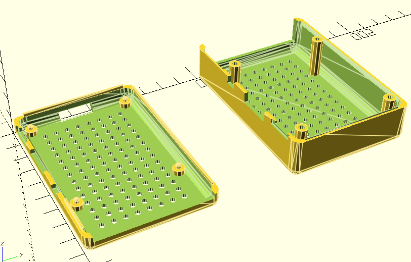
- Update: ventilation holes can now be enabled.
- I’ve not even considered a Pi 5 given the cooling requirements and so on.
I’ve also included a couple of test modes to do things like show the cutouts as solid items to help with positioning and spacing; and to take a large chunk out of the main flat body of the top and bottom for a quicker print to test positions.
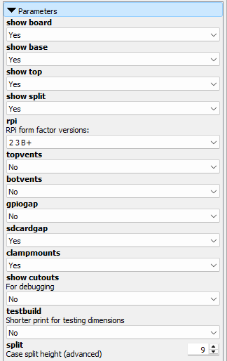
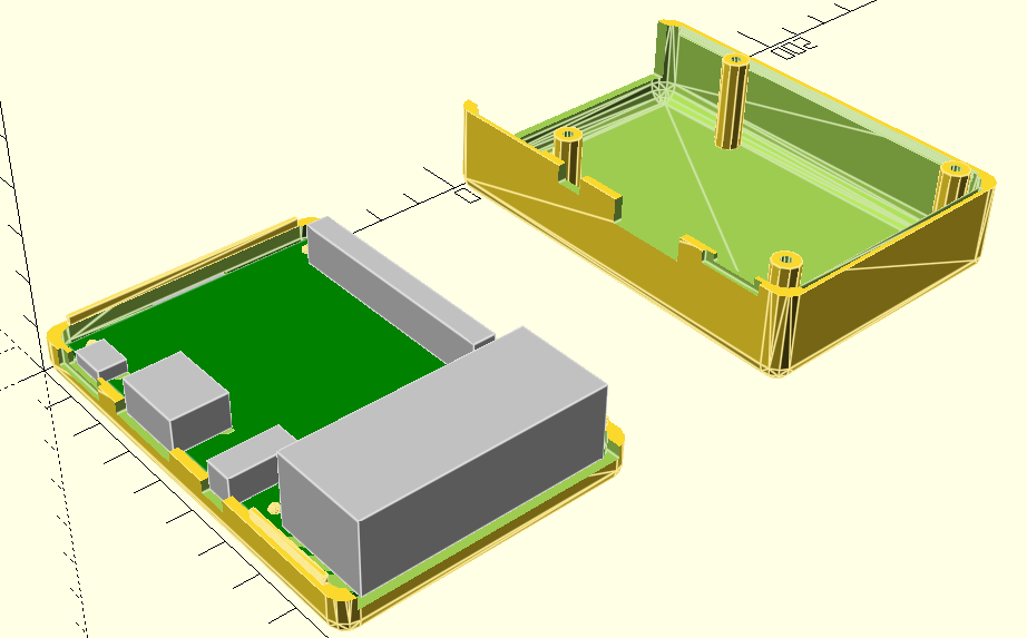
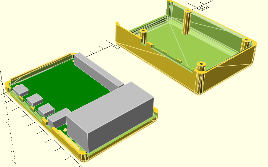
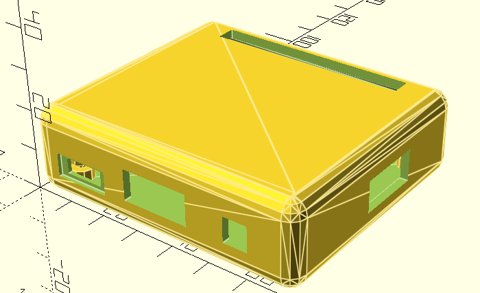
The Results
The main OpenSCAD file – RPi AB Case.scad – will support the built-in customizer to select the board and the various view and configuration options.
Raspberry Pi 3 A+
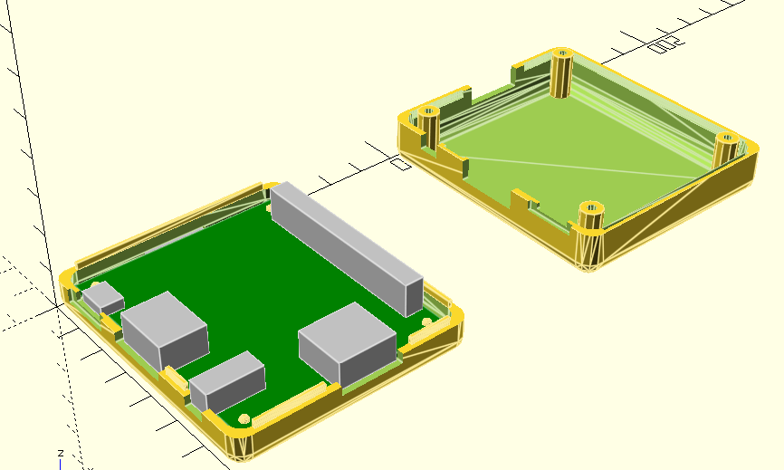
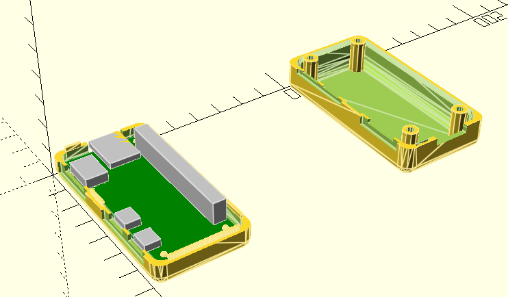
Raspberry Pi 2, 3 B+
Raspberry Pi 4
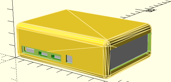
Raspberry Pi Zero
Examples of the other options.
Adding Custom Add-on Boards
The latest version of the code includes the option to define an additional custom add-on board, which I play to use for some of my own PCBs.
There is a section in the source that allows a custom board to be defined, for additional cutouts to then be specified for that board, and for adjustments to be made for the total size of the box to accommodate the custom board.
This all happens within the sections marked as follows:
////////////////////////////////////////////////////////////////////
//
// Custom additional boards/cutouts can be added here
//
////////////////////////////////////////////////////////////////////#

// rest of the custom definition and code

////////////////////////////////////////////////////////////////////
//
// Main RPI SCAD definitions
//
////////////////////////////////////////////////////////////////////
include <RPIABCaseModule.scad>
The main way to add a custom board and its devices is to update the following:
mdopt = 0;

md_boards = [
[0,0,0]
];
md_board = md_boards[mdopt];

md_gpio    = [[ 7.2,50.0, 0.0],[51.0, 5.1, 9.0],[ 0.0, 0.0, 0.0],[ 0.0, 0.0, 0.0],0];
md_gpio_e  = [[ 7.2,50.0, 0.0],[51.0, 5.1, 9.0],[ 0.0, 0.0, 0.0],[ 0.0, 0.0, 0.0],0];

md_dev = [
//[md_gpio],  // Board option 0
];
md_dev_e = [
//[md_gpio_e],  // Board option 0
];

md_devices = md_dev[mdopt];
md_extras  = md_dev_e[mdopt];
md_pad = [0, 0, 0];
md_ext = [0,0,0];
As devices are defined mirroring the md_gpio and md_gpio_e entries, they can be added to md_dev and md_dev_e as required. The definitions follow the same pattern as for the main RPi boards, but there is an additional final parameter which can be used to request a circular cutout rather than a rectangular one. This can currently only be used to request a circular profile in the x-y plane, but is useful for LEDs, buttons, pots and so on in the top.
Its a little complicated, but there are some comments in the template file, and there will be some real options added shortly.
Closing Thoughts
I think this will be a really useful basis for me being able to build some cases for some of my MiniDexed synths now.
The “cutout devices” approach and additional padding seems to allow me to add in device definitions for the encoder, display, MIDI sockets and buttons for my PCBs for MiniDexed, so they should be published soon.
Finally a big thank you to the authors of those three original designs for the inspiration and for sharing their ideas and techniques in a way that allows me to build on them for my own design.
Kevin
