I’ve a few EuroRack power supplies now, and most of them have a few things in common:
- Require an AC to AC “wall-wart” (typically 12VAC or above).
- Use diodes for half-wave rectifying and a large bank of capacitors for smoothing the resulting output.
- Use a 7912 and 7812 for -12V and +12V supply, and some add in a 7805 or 78L05 for +5V.
- Seem largely based on the same Music from Outer Space circuit by the legendary Ray Wilson, which is described in detail here: https://musicfromouterspace.com/analogsynth_new/WALLWARTSUPPLY/WALLWARTSUPPLY.php.
But I wanted something that had a slightly different set of dimensions to the ones I have and ideally would have a couple of 16-pin EuroRack power connectors already built in. So this project was the result – my own take on the MFOS design.
Given my growing, but still very limited, knowledge and experience of electronics, and the fact that I know I know enough to be dangerous, this isn’t going to be something I’m uploading the design for.
If you want a EuroRack PSU I strongly suggest going to someone who knows what they are doing and if you want a cheap, DIY, one, I can recommend looking at the following:
- Frequency Central: FC Power
- Polykit: EuroRack Power Supply
I have both of these, and they seem to work well, but there are many others on Tindie and similar places.
Warning! I strongly recommend using old or second hand equipment for your experiments. I am not responsible for any damage to expensive instruments!
If you are new to electronics, see the Getting Started pages.
The Circuit
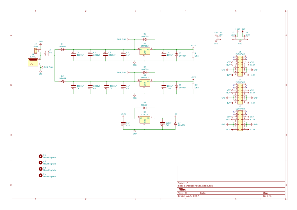
As I understand things, this works as the 12 VAC power supply will be supplying +/- 12V RMS, with a peak of something up to around +/- 17V. When rectified by the diodes (i.e. only the positive or negative half of the signal is taken) and smoothed out via the bank of capacitors, this means there is still greater than 12V going into the 7812/7912 which means they are able to put out a useful, steady, +12V/-12V respectively.
There is a lot more detail on the MFOS page, but this is the core of what I’ve taken away from it.
I’ve opted to include a 5V supply too and want three 16-way power connectors. I’ve also left it open to wire in an on/off switch.
I was in two minds about including LEDs. In the end I’ve broken out each power rail to a 2-pin jumper which serves two purposes. It can be used to solder a fixed wire to each of the power rails rather than use the 16-way connectors; or it could be used to connect a LED and suitable resistor.
I have left in footprints for the two 2K4 load resistors from the MFOS circuit, although these are not strictly necessary as I understand things (see later).
I’ve included both a barrel jack socket and screw terminals.
As is common with all these designs, this will require a 12VAC to AC wall adaptor, ideally rated at 1A or so.
Note – the idea behind using three large capacitors for the smoothing/filtering is that they effectively will make up a single larger capacitor. For lower current draws – maybe for testing just one module for example, rather than supplying a whole rack, then it might be possible to just use one of the three, or maybe three lower-value (and thus smaller) capacitors and for the output to still be useful.
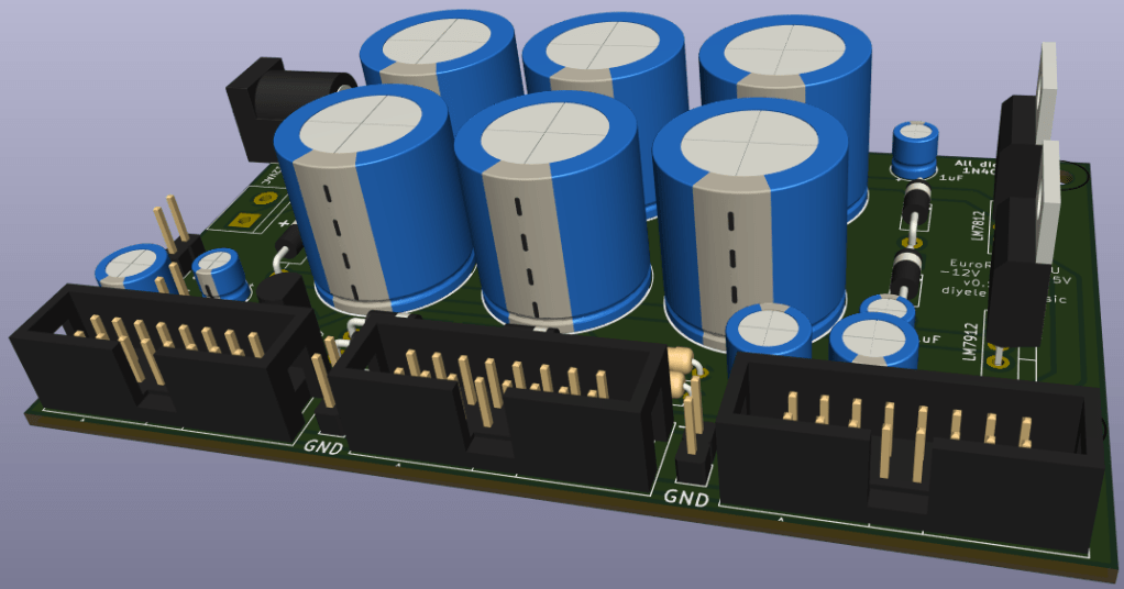
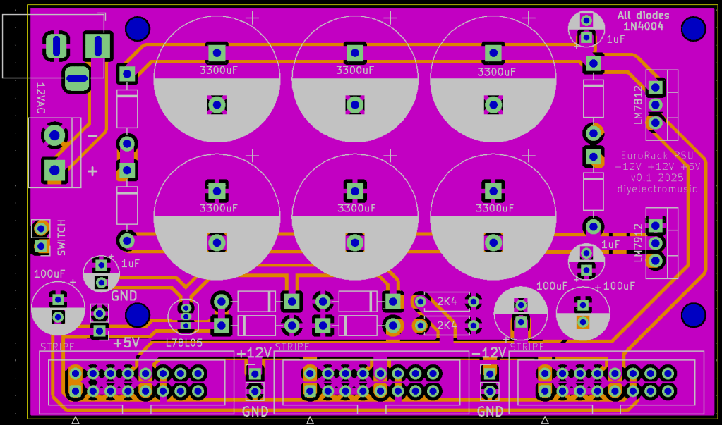
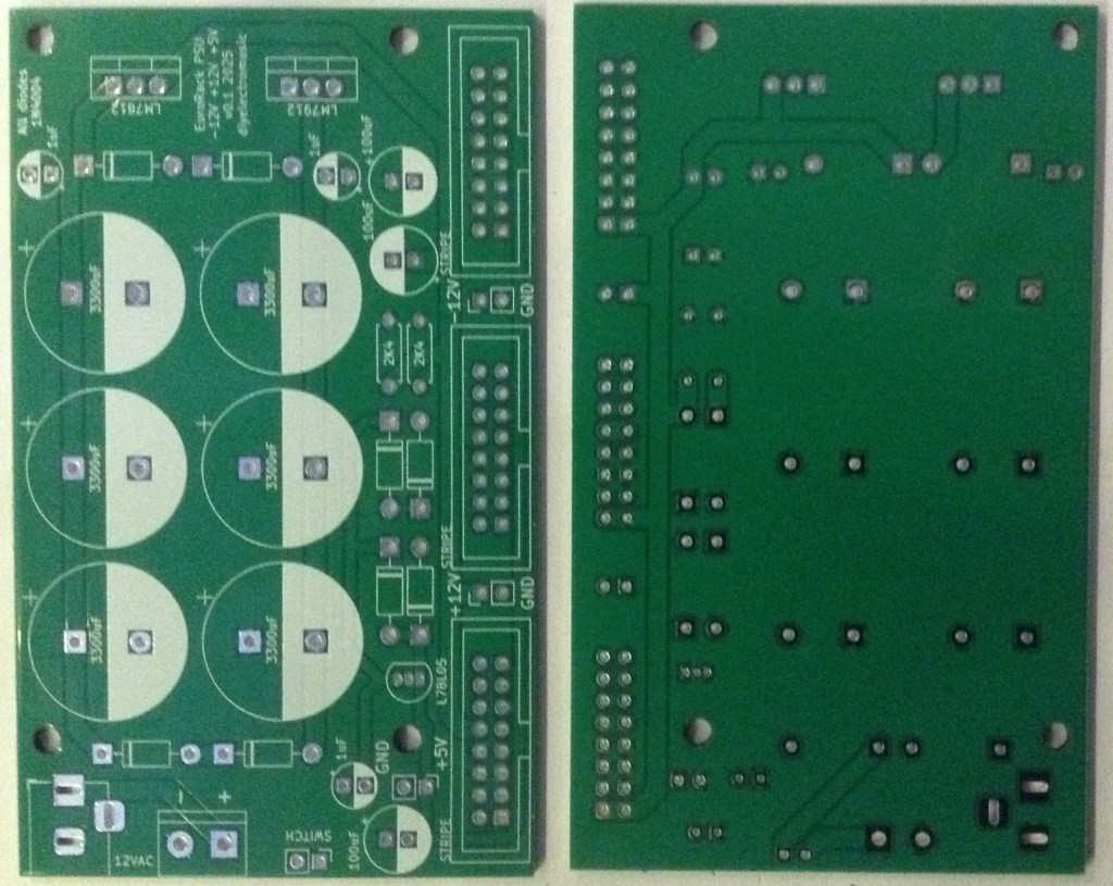
PCB Design
I wanted to keep this within a 100x100mm footprint but also wanted to include the three 16-way power connectors. Most boards I’ve seen that include connectors have them on the end, but I was more keen to have them all on the same side. Of course, this does mean that the board is “handed” and can only really be mounted one way around.
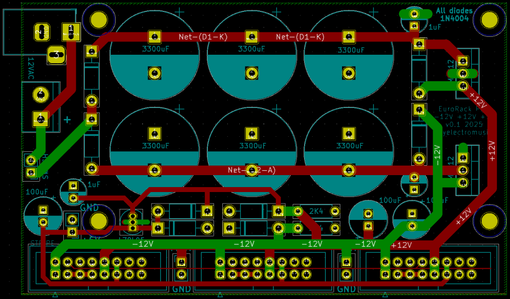
I’ve included four evenly spaced mounting holes and attempted to leave space around the two 12V regulators for a heat sink. With hindsight it would have been more useful to have the holes supporting the three EuroRack connectors a bit more.
I’ve taken the lead from the Frequency Central design and used a 78L05 with a TO-92 footprint (what I tend to think of as “like a transistor”) rather than the larger TO-220 footprint of the others. This does mean that the current draw from the 5V side will only be ~100mA or so, whereas the bigger versions can in principle draw up to 1A, although that will be limited by the capacitor of the 12VAC supply.
There are a few places where I’ve included extra tracks to bolster the GND connections. I wasn’t particularly happy about how the two 12V tracks largely cut-off the GND links of the 16-way connectors, but hopefully the GND fills mean that will work out ok.
As I say, I’ve left in the footprints for two load resistors (the two 2K4 ones) but as explained in the MFOS write-up these are optional and only required if there are issues starting up. Apparently the regulators need some load to reach a useful output level and if no modules are connected, having load resistors here helps. Without the resistors, with no modules plugged in, it won’t be possible to measure accurate voltage levels at the outputs.
I believe this design should work ok for me, but I don’t have any confidence in my knowledge of what is actually required in a power supply, so I won’t be publishing the files as usual for this one. In particular, I’m not confident in things like how the GND is managed and optimal placing of the capacitors, but I’ll see how things go. I expect this will be fine for my own “Lo-Fi” playing around.
So, just to be clear – this is a DIY project for use with DIY modules, and NOT for using with expensive modules. If you’ve spent lots of money on modules, then I’d also recommend matching your spending on a good, commercial power supply too.
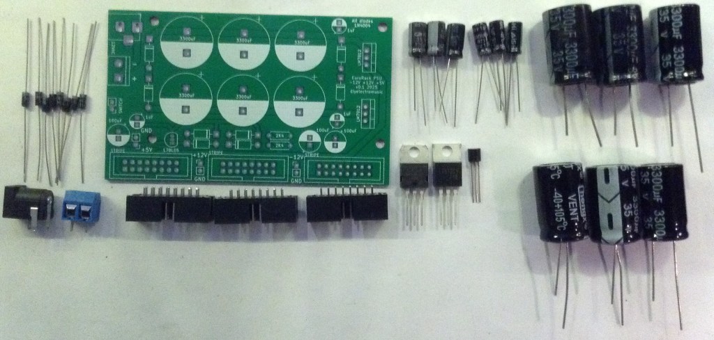
Build and Use
Unlike my other projects, I’m writing up these notes on the design so I can refer back to them, but won’t be publishing the resultant files or a build guide for this one.
No-one should be trusting me, with my level of knowledge, for a power supply. As I said at the start, do go and buy one from someone who knows what they are doing.
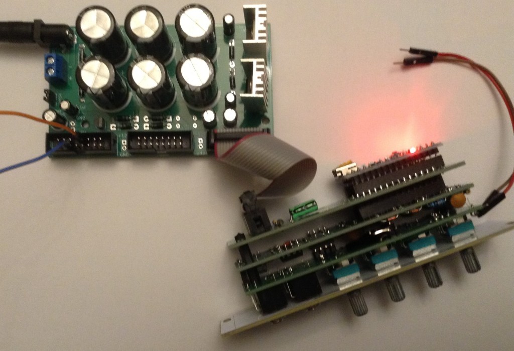
But just to prove I was brave enough to plug it in, here are some photos 🙂

Important notes:
- As previous mentioned this has to be used with a 12VAC AC to AC “wallwart”. It must NOT be used with a AC to DC one.
- When the power is turned off, the voltage lingers for up to 30 seconds thanks to that bank of capacitors. This is one reason that adding an LED might be quite useful – just to make that clear!
And just to repeat – this is just for my messing around. I don’t plan to be using this with anything expensive.
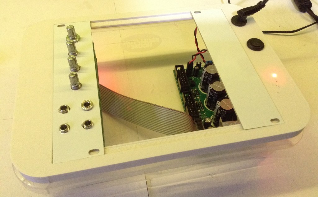
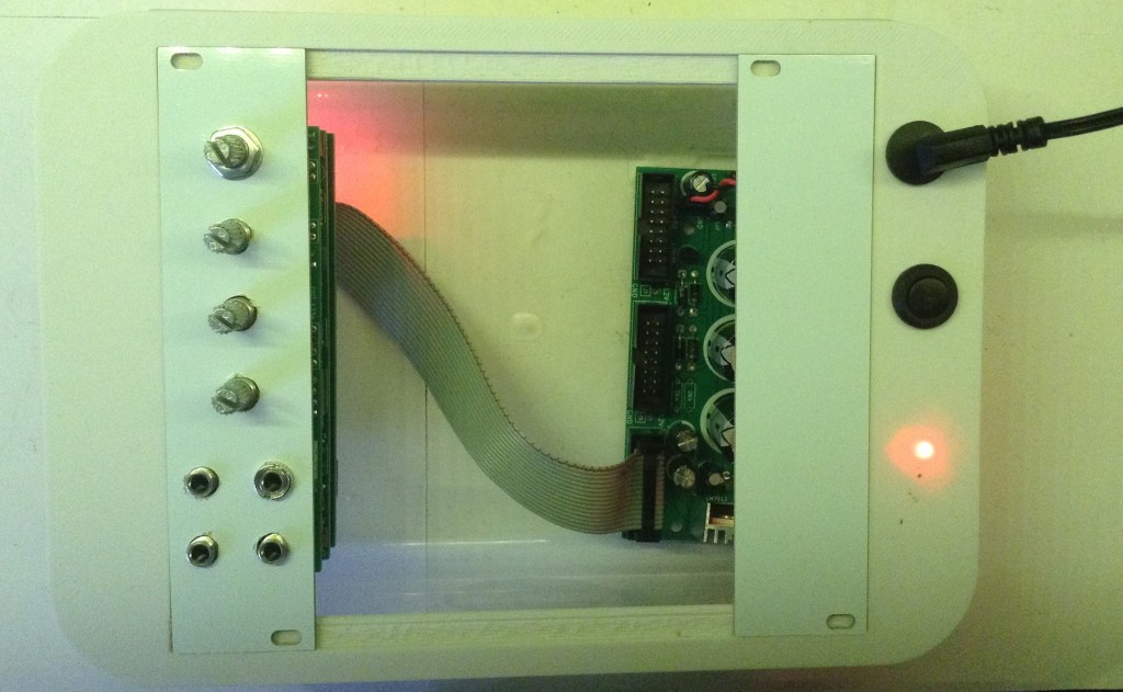
With the Cake Box Case
I’ve installed this into my CakeBox 30HP EuroRack Lid. It just needed a couple of holes for a power switch and DC jack socket, which I connected into the screw terminal block on the power supply.
I’ve also added a small (3mm diameter) red LED and 1K resistor which I soldered to a jumper header which I added to the 5V/GND breakout pads of the power supply.
I have a couple of M3 mounting sticky pads on order which I’ll use to fix the PCB into the box.
Closing Thoughts
I’ve always tried to stay away from power supplies. I’ve dabbled with some simple 7805-based circuits here and there, but have never attempted anything more complex than that.
This one benefits from a lot of “prior art” out there, but as always, I myself don’t have the electronics knowledge to know which is likely to be any good. Instead I’m going on the reputation of both MFOS and existing products like the Frequency Central board and attempting to learn from some of the design choices made in those products.
Ultimately, a poor supply will almost guarantee a noisy signal chain, so for any proper audio application, a proper tried-and-tested, quality, power supply is hugely beneficial. And this isn’t that.
So as I say, I don’t want this up as something to be used by someone who doesn’t already know more about the theory and practice than I do. And in that case, I’m sure those people are perfectly capable of designing their own power supply PCBs.
But it should do me well for a simple test supply for my experiments.
Kevin