Here are the build notes for my Arduino AY-3-8910 Shield Design.

Warning! I strongly recommend using old or second hand equipment for your experiments. I am not responsible for any damage to expensive instruments!
If you are new to electronics and microcontrollers, see the Getting Started pages.
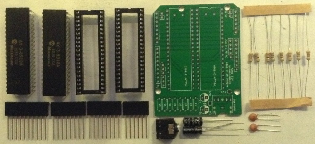
Bill of Materials
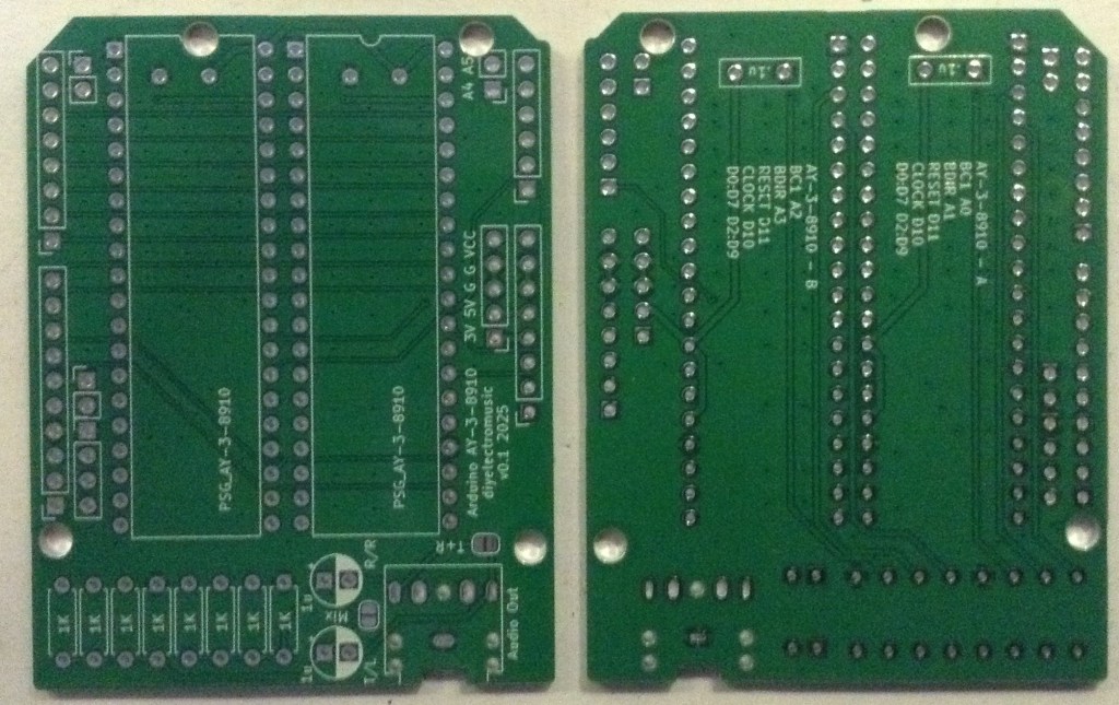
- Arduino AY-3-8910 Shield PCB (GitHub link below)
- 2x AY-3-8910 or YM2419 devices (see notes on sourcing here: Arduino and AY-3-8910)
- 8x 1KΩ resistors
- 2x 100nF ceramic capacitors
- 1x or 2x 1uF electrolytic capacitors
- 1x 3.5mm stereo TRS socket (see photos and PCB for footprint)
- Arduino headers: 1x 6-way; 2x 8-way; 1x 10-way pin or extended headers as required
- Optional: 2x 40 pin wide DIP sockets (highly recommended)
If both chips audio outputs are to be combined, using the solder bridges, then only one 1uF electrolytic capacitor should be used.
Build Steps
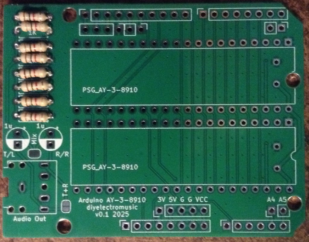
Taking a typical “low to high” soldering approach, this is the suggested order of assembly:
- Resistors.
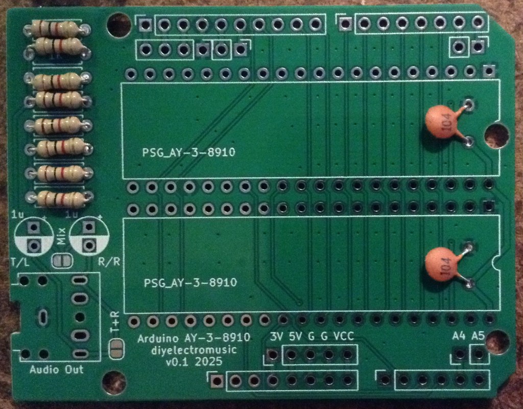
- Disc capacitors (see notes below).
- DIP sockets (if used) and TRS socket.
- Electrolytic capacitors.
- Arduino headers.
There are two solder bridge jumpers which can be used for the following:
- To mix all channels from both chips onto the same output.
- To combine left and right channels for the TRS socket.
By default, one chip goes to the left audio output and one goes to the right, but it is possible to combine them into a single mono output. But then there is another choice: combine the left and right audio channels (tip and ring) for the TRS socket; or leave all outputs just to the tip of the socket.
If these options are being considered, then one of the output electrolytic capacitors should be omitted too. More details below.
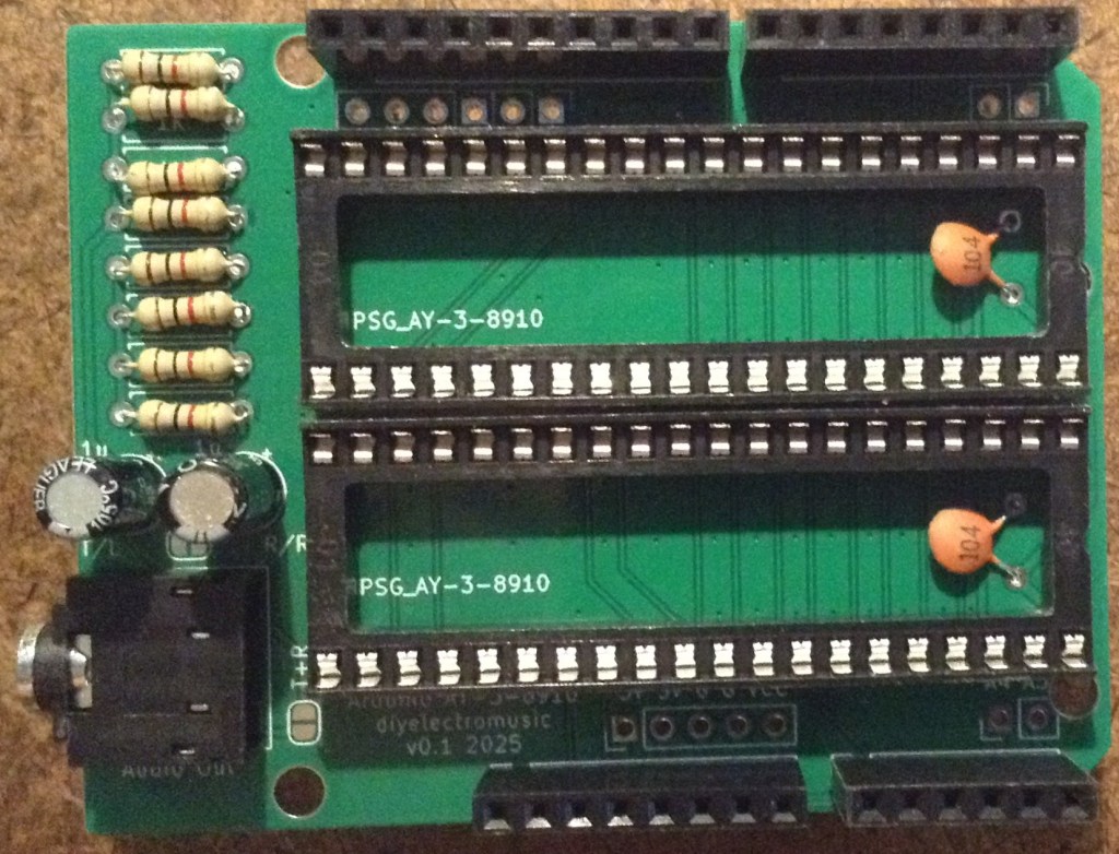
Here are some build photos.
The ceramic capacitors are actually shown as being installed on the underside of the board, but depending on the 40 pin DIP socket used (or not) it may be possible to install them on the top side of the board as I’ve done below.

I’ve used “extended headers” which give me a breakout for the Arduino GPIO on the top of the board. If simple pin headers are used, then care should be taken about the height of the board and avoiding the possibility of the resistors shorting out on the USB socket of the Arduino.
Solder jumper options
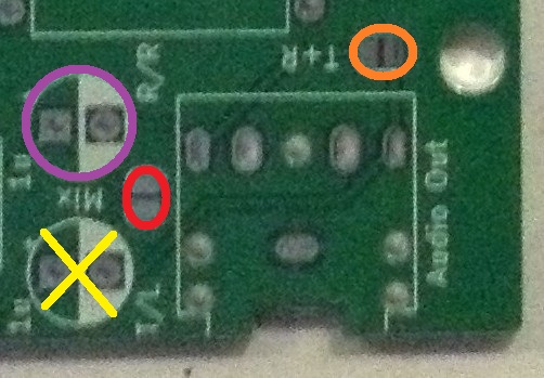
For mono operation:
- Only install electrolytic capacitor highlighted in PURPLE. Do not install the capacitor with the YELLOW cross.
- Bridge the solder jumper highlighted in RED.
For mono socket operation, i.e. TIP and GROUND only, leave the solder bridge highlighted in ORANGE unbridged. This allows a mono jack lead to be used as RING is unconnected in the socket and can be ignored.
To take the mono signal into a stereo socket, i.e. TIP, RING and GROUND but with TIP and RING having the same mono output signal, solder the bridge highlighted in ORANGE. This allows a stereo jack lead to be used and both channels will received the same output signal.
Testing
I recommend performing the general tests described here: PCBs.
Once everything appears electrically good, a variation of the test application from my AY-3-8910 Experimenter PCB Build Guide can be used that will play a chord on both of the devices at a different octave.
Note: the GPIO usage of the Arduino is printed on the back of the PCB and listed in the Arduino AY-3-8910 Shield Design.
PCB Errata
There are no known issues with the PCB at present.
Enhancements:
- None
Closing Thoughts
This seems to work fine and is a lot simpler than my quad board if some simple experimentation is required.
I still haven’t gotten around to building some real applications for any of these boards yet though, so ought to get on to that.
Kevin
