Having spent quite a bit of time with an Arduino hooked up to an SP0256A-AL2 on a solderless breadboard, and now that I’ve got some ideas for how I want to sort out the clock, I thought it time to create a PCB to save the unreliable wiring getting in the way!
Warning! I strongly recommend using old or second hand equipment for your experiments. I am not responsible for any damage to expensive instruments!
If you are new to electronics and microcontrollers, see the Getting Started pages.
The Circuit

This is the basic circuit I’ve been using since Part 1 but I’ve added in an option to support the SI5351 from Part 5 instead of the oscillator, too. A solder jumper selects the clock source – there is no default setting.
There is also a (default closed) solder jumper on the RESET line in case there is a need to separate out the reset of the SP0256A-AL2 from the Arduino.
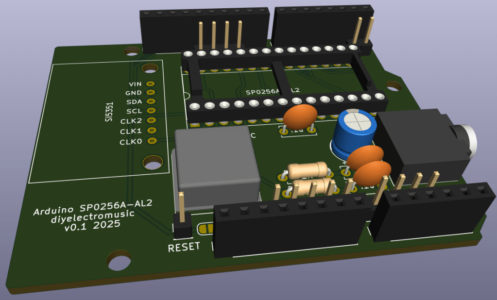
PCB Design
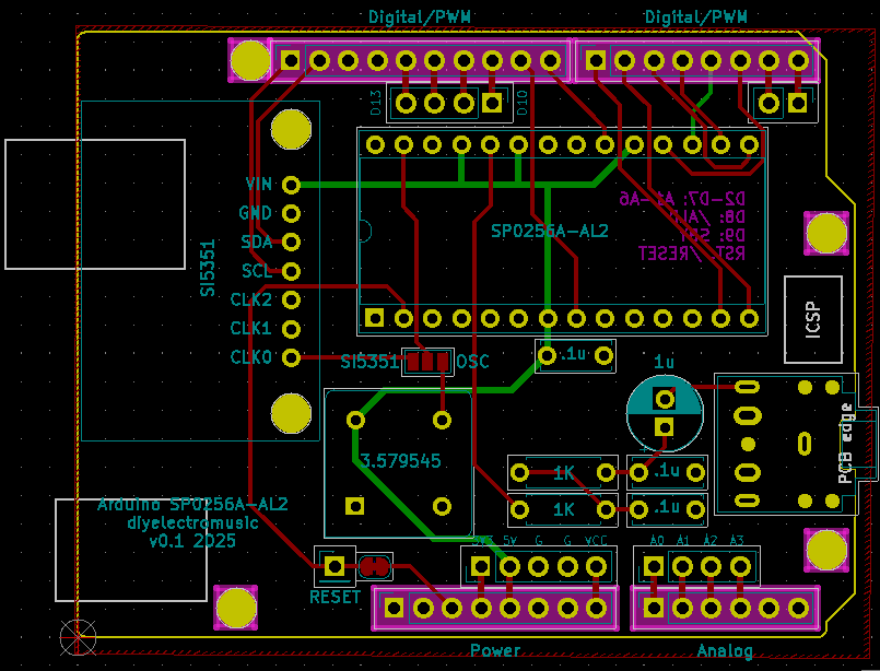
The PCB design is relatively straight forward. Using an Arduino Uno Shield template, all the components have fitted in quite well.
I had to create a custom symbol and footprint for both the SP0256A-AL2 itself and the SI5351 module I’m using.
The following GPIO pins are in use.
| Arduino | SP0256A-AL2 |
| D2-D7 | A1-A6 |
| D8 | /ALD |
| D9 | SBY |
| GND | VSS, A7, A8, TEST, OSC2 |
| +5V | VDD, VDI, SE, /SBY_RESET |
| /RESET | /RESET |
| SI5351 (Optional) | |
| A4 | SDA |
| A5 | SCL |
| GND | GND |
| +5V | VIN |
As already mentioned, the link between the two /RESET pins is via a solder jumper and pin header connection which can be broken if required.
I’ve added in additional breakout headers for all GPIO that isn’t connected to the SP0256A-AL2: D0-D1, D10-D13, A0-A3.
I’ve not included A4-A5 as these are connected to the SI5351 (if used).

Closing Thoughts
Hopefully this is a fairly straight forward design with no major surprises.
Kevin
