Here are the additional build notes to use my Waveshare Zero Multi Display PCB in “expander” mode to support up to eight displays.
- Waveshare Zero Multi Display PCB Design
- Waveshare Zero Multi Display PCB Build Guide
- Arduino with Multiple Displays – Part 3
Warning! I strongly recommend using old or second hand equipment for your experiments. I am not responsible for any damage to expensive instruments!
If you are new to electronics and microcontrollers, see the Getting Started pages.
Bill of Materials
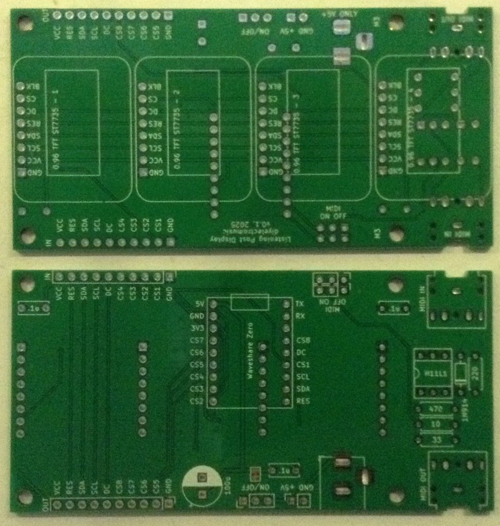
- Waveshare Zero Multi Display PCB (GitHub link here: Waveshare Zero Multi Display PCB Build Guide)
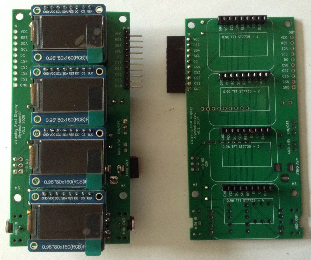
- 4x SPI 0.96″ 80×160 (RGB) IPS TFT displays
- Capactitors: 2x 100nF ceramic
- Optional: 4x 8-way pin header sockets – strongly recommended. PH5.0 “short” headers are best.
- 1x 10-way right angle pin headers
- 1x 10-way right angle pin header socket
Build Steps
It largely doesn’t matter what order things are soldered on. I did them in the following order
- Right angle pin header.
- 8-way PH 5.0 pin header sockets for the displays
- 2 ceramic capacitors
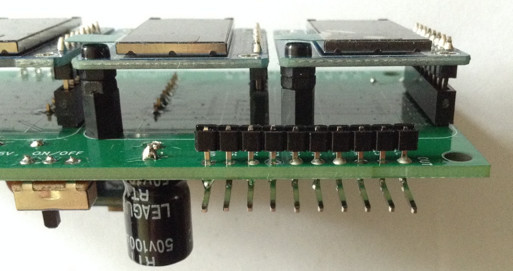
The expander board photos are shown below.
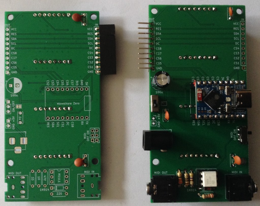
Note that when adding the right-angle pin headers to the main board, as described in Waveshare Zero Multi Display PCB Build Guide, they will need to be soldered flush to the PCB and not left separated by the plaster spacers.
To do this, I pushed the spacers to the edge of the bent pin headers and then pushed the whole thing through the PCB prior to soldering. Once soldered, the plastic spacers can be removed and the pins clipped, but in the photo below the spacer has been left.
Testing
The updated sketch described in Arduino with Multiple Displays – Part 3 can be used to test the expander board with eight displays in total.

A Note About Power…
When running 8 displays, I can feel my Waveshare board getting quite hot…
The displays are all powered from the 3V3 line. The Waveshare schematic shows that the 3V3 line comes from a ME6217C33M5G which is powered from the VBUS/5V line as shown below. Recall that the VBUS/5V line comes ether from the USB socket or an external connection to the VCC pin.

That regulator can supply up to 800mA according to the datasheet.
In terms of current usage of a ST7735 display, the datasheet states the following:
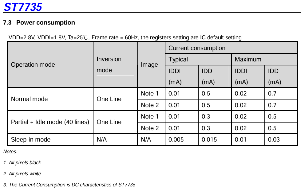
I have to say, I’m not really sure what that is telling me. Is that up to 0.7mA per line displayed? What if all lines are on – are these displays scanned or “all on”? There are potentially 80 lines on a display…
Ah, this post: https://wiki.dfrobot.com/0.96_Inch_160_80_Color_SPI_TFT_Display_SKU_DFR0847 suggests that the display only consumes 15mA full screen.
Powering eight displays and a Waveshare Zero ESP32-S3 via the USB connection through one of those current measuring USB pass-through devices, seems to show a continuous current consumption of 200mA.
Removing four of the displays, that appears to drop down to 110mA, so I think in my case it is a little more than 15mA – perhaps nearer 20mA per display.
I can’t quite work out if it is the regulator or the ESP32-S3 itself getting hot. My sophisticated sensor (finger) hasn’t the resolution to work it out. But it is definitely not as hot powering four displays as eight.
I am now wondering if I should have included an independent regulator on the board to generate a 3V3 supply rather than use the one onboard the Waveshare Zero.
Closing Thoughts
I really ought to think about some of these design issues up front. One day 🙂
In general terms this seems to work really well. I’d like to know a little more about what is getting hot, as, as far as I can see, “on paper” the components ought to be able to cope.
I have an application in mind for all these displays. There is a small clue in the filenames of the PCB, but it remains to be seen if I get right to the end of the idea or not.
For now, these are quite neat ways to drive several small, full colour displays.
Kevin
