After getting the Arduino and SP0256A-AL2 working I wondered if I could repeat the trick from the Arduino and AY-3-8910 and have the Arduino generate the required clock signal for the SP0256A-AL2. This post starts to look at that question.
- Part 1 – Basic introduction and getting started
- Part 2 – Arduino programmable clock
- Part 3 – Using a Raspberry Pi Pico as a programmable clock
- Part 4 – Using a HC4046 PLL as the clock
- Part 5 – Using an I2C SI5351 programmable clock
- Part 6 – Adding MIDI
Warning! I strongly recommend using old or second hand equipment for your experiments. I am not responsible for any damage to expensive instruments!
If you are new to Arduino, see the Getting Started pages.
Parts list
- Arduino Uno
- SP0256A-AL2 speech synthesizer chip
- 2x 1KΩ resistors
- 2x 100nF capacitors
- 1x 1uF capacitor
- 1x 3.5mm jack socket
- Breadboard and jumper wires
The Circuit
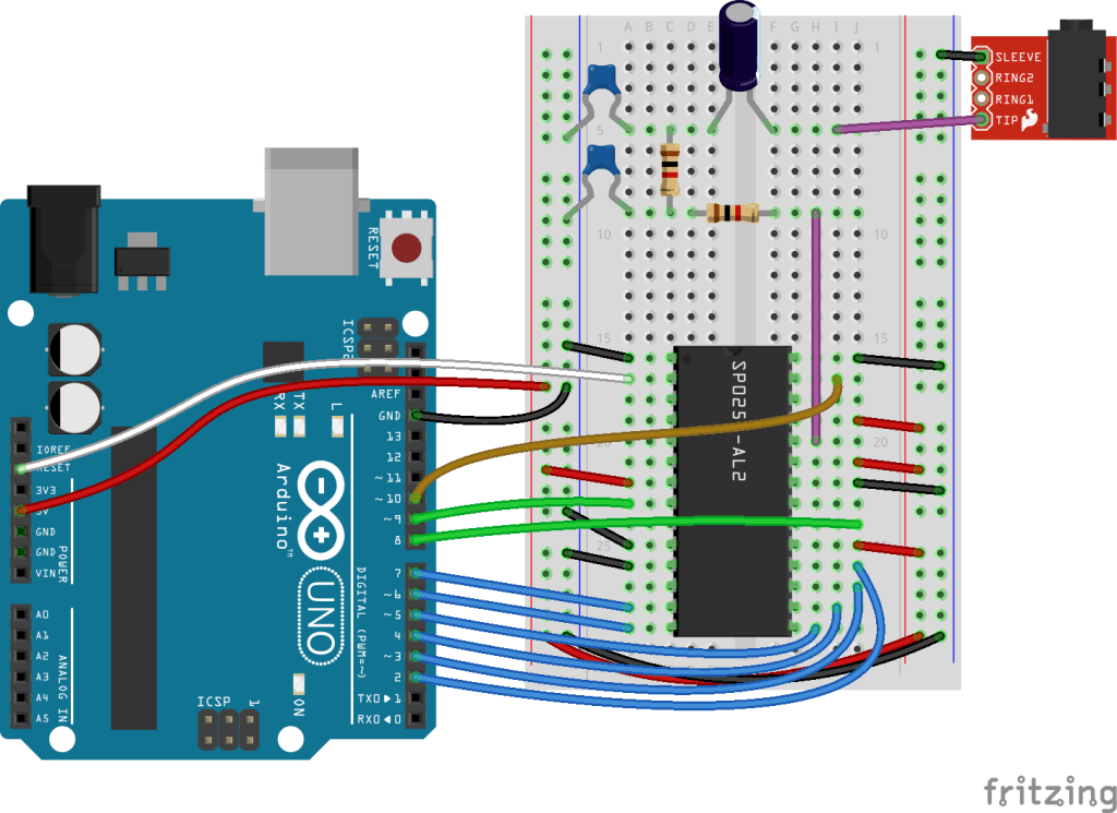
This is basically the same setup as the previous post, but instead of the 3.579345 MHz oscillator, the clock input of the SP0256A-AL2 is connected to the Arduino D10 pin.
D10 is internally connected to OC1B, or the “B” compare match output of Timer 1 of the ATMega328P.
The Code
To get a clock signal of any kind on one of the output pins requires use of the ATMega328’s timers – in this case Timer 1. This is a 16-bit timer.
To generate an automatic (i.e. with no code driving it once it is set up) square wave signal on the Arduino’s output pin requires the timer to be connected to an output pin to generate a 50% duty cycle PWM signal.
The PWM peripherals can be configured to toggle an output pin when the timer expires, but that therefore requires the PWM to be running at least twice as fast as the required frequency.
From the SP0256A-AL2 datasheet, it has this to say about clocks.

There isn’t a lot to go on here – basically it assumes a 3.12MHz clock with a 48-52% duty cycle for the square wave.
A typical application circuit would be the following (again from the datasheet):
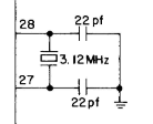
And the final word on oscillators is in the pin descriptions:
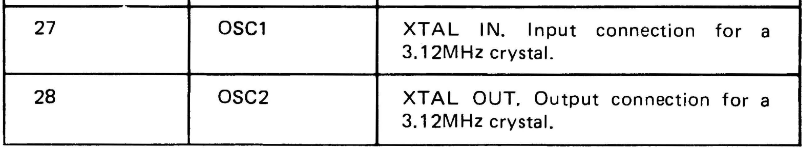
The options for creating a 3.12 MHz clock with an Arduino PWM output are pretty limited, due to the following:
- The faster clock for PWM is related to the system IO clock speed of 16MHz, when running with no “prescalar” to drop it down in frequency.
- When running at 16MHz, lower frequencies are obtained by using the “compare match” approach. The timer will reset and the output pin will toggle when a counter match occurs. The counter will count in integer units of the core 16MHz frequency.
- As the output pin will toggle on compare match, the timer must run at twice the frequency of the required clock signal. This allows one period for a HIGH output and one period for a LOW output to generate the required square wave output.
The PWM square wave frequency is given by the following formula (as per the ATMega328P datasheet for Timer 1,3,4):
- Freq = FreqClk / (2 * prescalar * (OCR1B + 1))
Given the above, with a FreqClk of 16MHz, the following are the only real options for a PWM-driven square wave as a clock for this application:
| OCR1B compare value | Resulting clock frequency |
| 0 | 8 MHz |
| 1 | 4 MHz |
| 2 | 2.7 MHz |
| 3 | 2 MHz |
| 4 | 1.6 MHz |
| 5 | 1.3 MHz |
So there isn’t a lot of choice, and nothing particularly close to the required 3.12 MHz, although 2.7 MHz is the closest and would probably do if required.
To configure the above requires the following code:
#define SP0_CLOCK 10 // D10
void clockSetup () {
pinMode(SP0_CLOCK, OUTPUT);
digitalWrite(SP0_CLOCK, LOW);
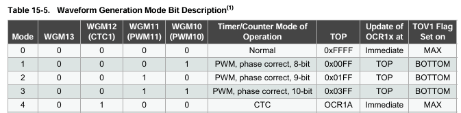
TCCR1A = (1 << COM1B0);
TCCR1B = (1 << WGM12) | (1 << CS10);
TCCR1C = 0;
TIMSK1 = 0;
OCR1AH = 0;
OCR1AL = 1;
}
This configures Timer 1 in Clear-Timer-on-Compare (CTC) mode with no prescalar, toggling OC1B on compare match with the value in OCR1A.
Note: even though there are two pin outputs – OC1A on D9 and OC1B on D10 – which is used is determined by the COM1A/COM1B settings. Even when using OC1B, as I am here, it is still the match value in OCR1A that determines when the counter has reached its “top” value.

I updated the code to try each of the above values for OCR1A in turn and the result is the video at the start of this post.
void setClock (int clock) {
  OCR1AH = 0;
  OCR1AL = clock;
}
Closing Thoughts
It is interesting to note that the Arduino can in fact provide a clock that allows the SP0256A-AL2 to function, even if it is not particularly true to the original at this point.
But it does mean that there isn’t as much control over the pitch as I’d hoped. If I want to get to more of that granularity between 4 MHz and 2 MHz, I’ll have to find another way.
Kevin
