Here are the build notes for my Arduino Pro Mini MIDI USB CV PCB Design.

Warning! I strongly recommend using old or second hand equipment for your experiments. I am not responsible for any damage to expensive instruments!
If you are new to electronics and microcontrollers, see the Getting Started pages.
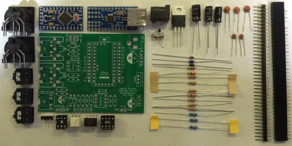
Bill of Materials
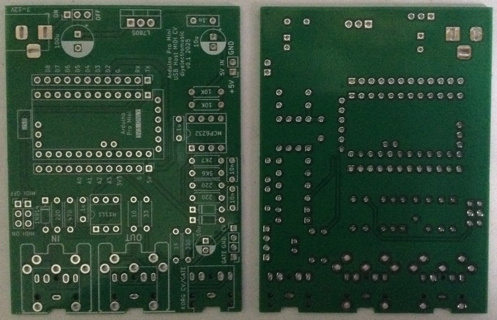
- Arduino Pro Mini USB MIDI Host CV PCB (GitHub link below)
- Arduino Pro Mini (3V3/8MHz version)
- Mini USB Host Shield 2.0
- 1x H11L1
- 1x MCP6232
- Diodes: 1x 1N4148 or 1N914 signal diode; 2x BAT43 Schottky
- Resistors: 10Ω, 33Ω, 1x 220Ω, 330Ω, 470Ω, 3x 1K, 2K7, 5K6, 2x 10K (*)
- Ceramic Capacitors: 4x 100nF (*)
- 1x 3.5mm stereo TRS
- Either 2x 3.5mm stereo TRS OR 2x 5-pin, 180 degree MIDI DIN sockets
- Pin headers
- Optional: 2x 12-way pin header sockets
- Optional: 1x 6-way DIP socket; 1x 8-way DIP socket
* The PCB shows the use of 2x 10nF and 2x 200Ω resistors for the PWM filter part, but 100nF and 1K work much better.
Optional: Power circuit
- 7805 regulator
- Electrolytic Capacitors: 1x 10uF, 1x100uF
- Ceramic Capacitors: 1x 100nF
- 1x SPST power switch 2.54mm pitch
Build Steps
Taking a typical “low to high” soldering approach, this is the suggested order of assembly:
- Diodes
- Resistors
- DIP sockets (if used) and TRS sockets (if used).
- Disc capacitors.
- Switches (if used).
- Jumper headers.
- Electrolytic capacitors (if used).
- DIN sockets (if used).
- 7805 (if used).
- Arduino + USB Host Shield (see notes below).
The Arduino Pro Mini and USB Host Shield need to be soldered together as a unit. If using header sockets, these will require longer header pins and will need soldering together as a single unit “off board”.
If not using sockets, normal pin-headers should suffice, in which case it is probably easier to solder the pin headers to the PCB and then add the USB Host shield, followed by the Pro Mini.
The USB Host shield requires a track cutting and a connection made from the Arduino’s VIN to the shields VBUS pad. See photos and discussion in the text.
Note: the PCB incorporates a capacitor on the CV PWM output to the TRS socket. This would be required if this was an audio signal to remove the DC bias. But as this is a CV output, the capacitor should be replaced with a simple wire link. More on that below.
Here are some build photos.
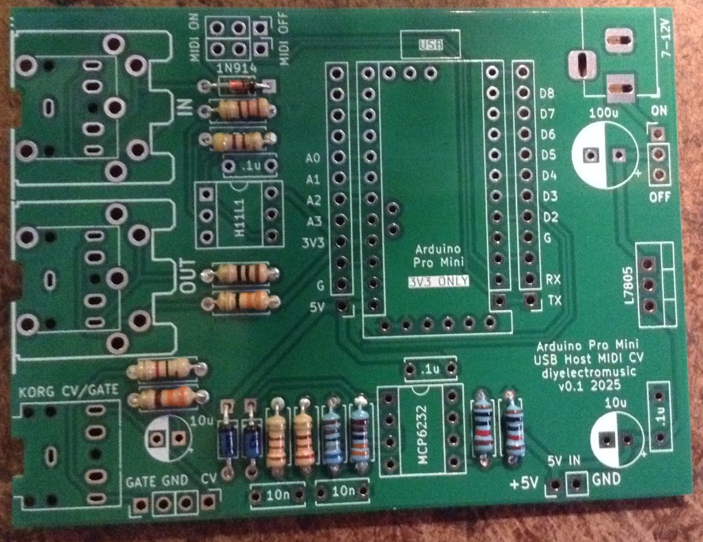
The two 220Ω resistors should be replaced with 1K instead.
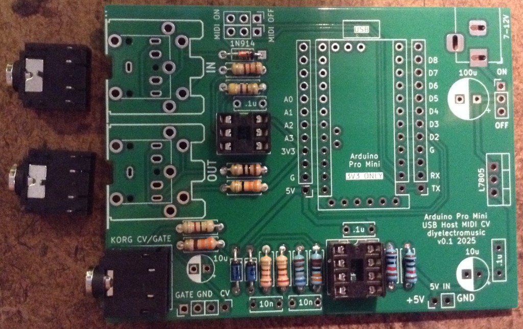
If using MIDI TRS sockets, these should be added, along with the CV/Gate socket, next with the (optional) DIP sockets.
I’m going to use MIDI DIN sockets, so they will be left almost to last.
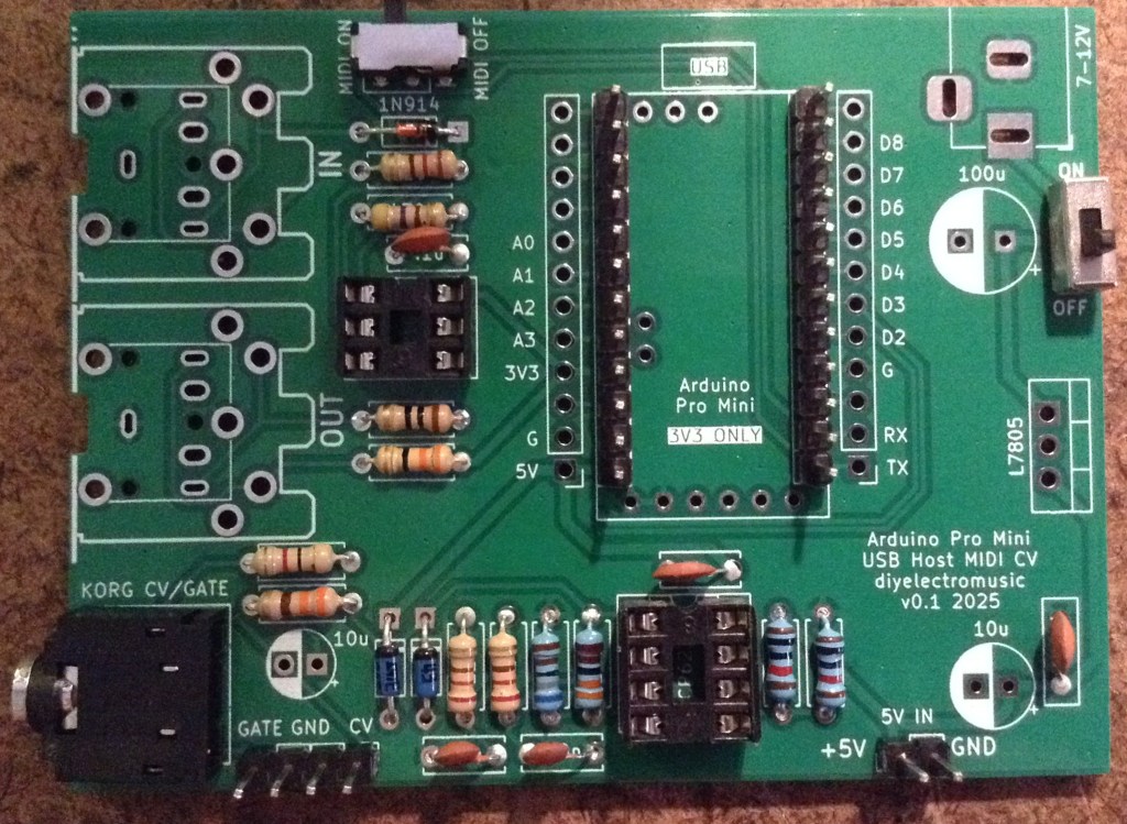
The MIDI on/off is required to disabled MIDI to allow sketch uploading to the Pro Mini. This can be replaced with 2×3 pin headers and jumpers, or if the Pro Mini will be removed for programming, even wire links.
I’m using a DPDT slider switch with a 2×3 2.54mm pitch.
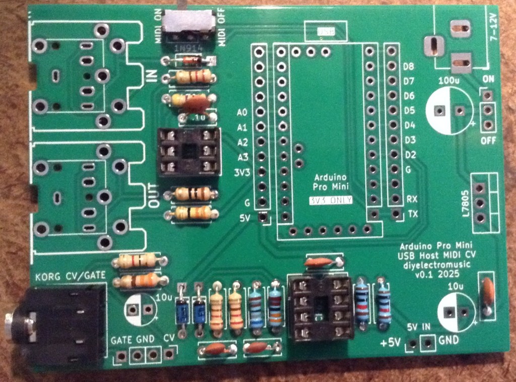
The two 10nF capacitors should be replaced with 100nF capacitors instead.
If using 2x 12-way header sockets for the Arduino, these can be added at the same time as other pin headers next.
I’m planning on soldering my USB Host shield and Pro Mini directly to the board, so the best way to do that seems to be to add the headers to the board, as shown below, then I’ll add the shield and Pro Mini later.
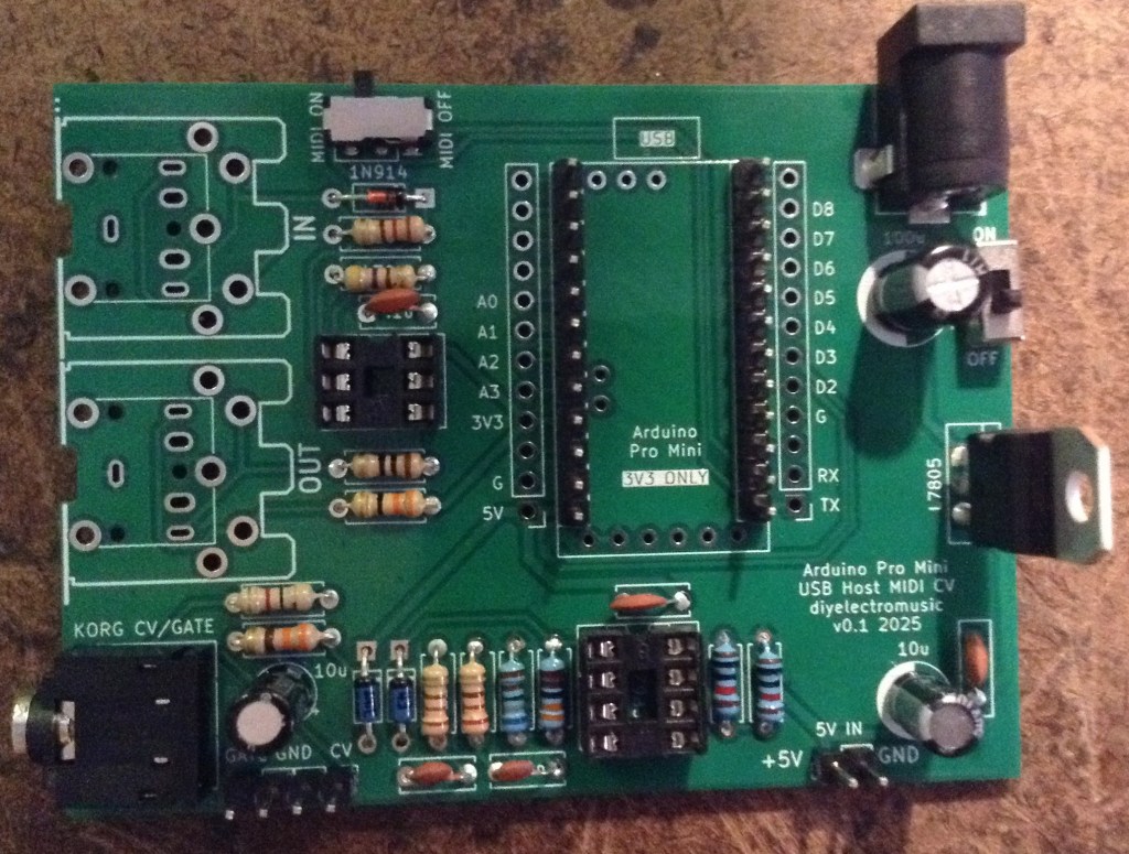
The power circuitry is optional. This allows a 7-12V DC barrel jack (centre positive) to be used to create the required 5V for the Pro Mini and USB.
Alternatively, there is a 5V/GND direct jumper header that may be used instead. This should not be used to power the board if the regulator is fitted, but can be used as a 5V source if required.
Note: as already mentioned, when adding the electrolytic capacitors, the 10uF next to the CV TRS socket should be left out and replaced by a wire link.

The full photo below shows the capacitor present – I had to remove it!
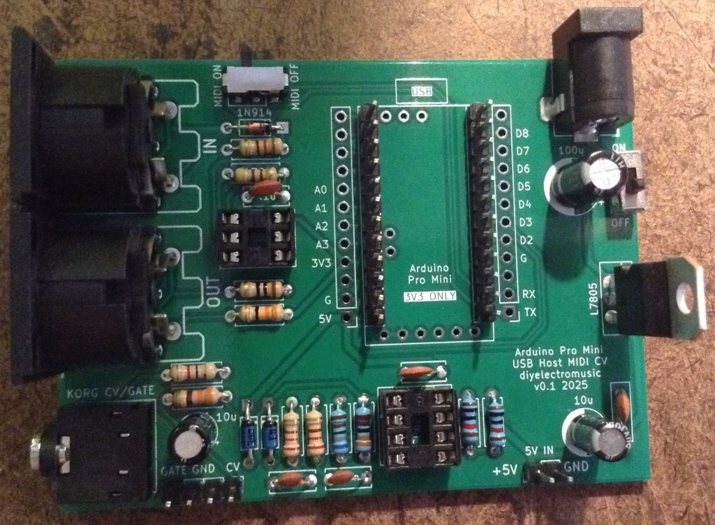
The MIDI DIN sockets, if used, are the last component apart from the Arduino itself.
I will be stacking the USB shield and Pro Mini, so the shield goes on next. Note: there is a track that requires cutting between the VBUS solder pad and the 2K2 resistor as shown below. Note, this track must not be cut between the USB socket and the VBUS pad…
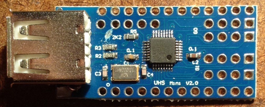
Cutting this track removes the connection between the USB VBUS lines and VCC on the PCB, which is running at 3V3. Once cut, a wire can then be soldered between the VBUS pad and the pin that will eventually connect to the Pro Mini’s VIN pin as shown below.
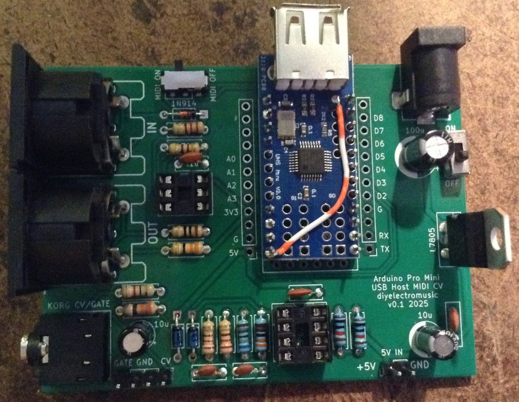
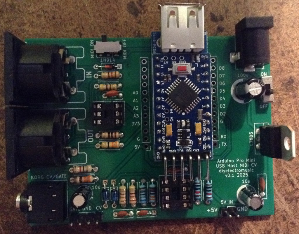
At this point the Pro Mini can now be added on top. I’ve not used any additional spacers, simply relying on the existing solder on the pin headers (from the USB shield) and the presence of the patch wire to distance the board enough. The pin headers themselves weren’t long enough, for me, to add proper plastic spacers, so I didn’t.
Testing
I recommend performing the general tests described here: PCBs.
The sample application section below lists some sketches that will test the various functions of the board.
An oscilloscope can be used to check the voltage output from the PWM signal.
PCB Errata
There are the following issues with this PCB:
- As already mentioned, there are two issues with the CV output circuit:
- The electrolytic capacitor should be replaced with a wire link.
- The 10nF and 220Ω resistors in the filter should be replaced with 100nF and 1K.
Enhancements:
- The CV and GATE signals are different levels at present. CV is 0-5V; GATE is 0-3.3V. Perhaps they ought both be 5V signals.
Sample Applications
The following GPIO pins are used with this PCB:
| D0/D1 | RX/TX for Serial MIDI |
| D2 | GATE output |
| D3 | PWM CV output |
| D9 | INT pin for USB Host shield |
| D10-D13 | SPI link to USB Host shield |
Here are some applications to get started with.
Note: I found that serial MIDI would not work when powered via the programming header, presumably because my programmer was controlling RX/TX. To test MIDI the board had to be powered via the barrel jack or 5V directly.
Also recall that MIDI needs to be OFF in order to upload sketches.
- USB MIDI: USB MIDI monitor code here.
- Serial MIDI IN: Simple MIDI monitor code here.
- Serial MIDI OUT: Examples -> USB Host Shield Library 2.0 -> USBH_MIDI -> USB_MIDI_Converter
- GATE Output: Examples -> 02.Digital -> toneMelody (it just produces a square wave)
- PWM Output: Arduino PWM Sound Output (even though this isn’t for sound!)
For the last two, some minor code changes are required.
For toneMelody, the pin used need changing from pin 8 to pin 2 in the tone() and noTone() calls.
For the PWM output, the following configuration options must be set:
//#define FREQPOT A0
//#define PIN_9_PWM_OUTPUT 1   // Uses Timer 1
#define PIN_3_PWM_OUTPUT 1   // Uses Timer 2
In both the GATE and PWM test, it is actually possible to hook up a speaker via a stereo 3.5mm jack to the CV/GATE TRS socket.
WARNING: If you do this, the speaker will be receiving a 0-5V signal on either the L or R outputs (depending on the test). This is a lot more than a line input signal (which is typically +/- 0.8V) so do not hook this up to standard audio input.
Alternatively, just check the signals via the GATE/CV jumper header with an oscilloscope.
The PWM output should be 0-5V. The GATE output should be 0-3.3V.
Use as a USB to CV/GATE Converter
The CV/GATE TRS output follows the standard set for the Korg Volca Modular (see Korg Volca Notes).
I show how to use this as a USB MIDI interface for a CV/GATE synth here: USB MIDI to Serial and CV/GATE.
IMPORTANT: Do not use this board with your Korg Volcas unless you know what you are doing, are able to validate all signals prior to connection yourself, and happy with the very real possibility that the board might do something that damages the Volca.
I am not an electronics person and will not be responsible for damage to expensive or treasured equipment. I only use cheap or disposable equipment in my own projects.
Closing Thoughts
Adding that capacitor was a case of me running on “autopilot” I think, but that is a straightforward fix, so no real harm done.
At the end of the day, this whole board is a little niche, even by my standards.
But it seems to work well enough that I can get on with writing some proper firmware for it now.
Kevin
