Here are the build notes for my EuroRack 6HP Daisy Seed MCU PCB.
Please Note: At the time of writing this has shown to be able to power up and nothing more. None of the IO or audio functions have been tested yet!
I’ll update this post once I have some test applications to show everything is working, but that will require a different build of my EuroRack 6HP MCU Experimenter Module I expect.

Warning! I strongly recommend using old or second hand equipment for your experiments. I am not responsible for any damage to expensive instruments!
If you are new to electronics, see the Getting Started pages.
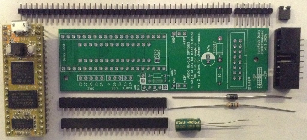
Bill of Materials
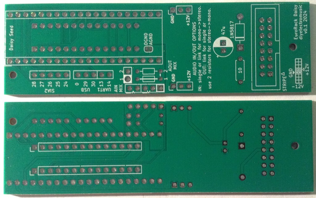
- EuroRack 6HP Daisy Seed MCU PCB (GitHub link below)
- Daisy Seed.
- 2x 20 way headers – PH5 headers recommended.
- 2x 14-way header pins and socket – PH5/9.5mm headers recommended (see my previous notes).
- Header pins.
- 1x 1N5817 Schottky Diode.
- 1x 10Ω resistor (1W or higher).
- 1x 47uF electrolytic capacitor.
- 1x 2×8 way shrouded pin header socket (EuroRack power).
- M2 mounting posts, screws, nuts as required.
- Jumper/connecting wires.
- Additional header pins and jumpers as required.
- Optional: 2x 1KΩ resistors for audio mixing stage.
Recall that this is designed to be used with the IO board from the EuroRack 6HP MCU Experimenter Module.
Build Steps
Taking a typical “low to high” soldering approach, this is the suggested order of assembly:
- Resistor and diode.
- Electrolytic capacitor.
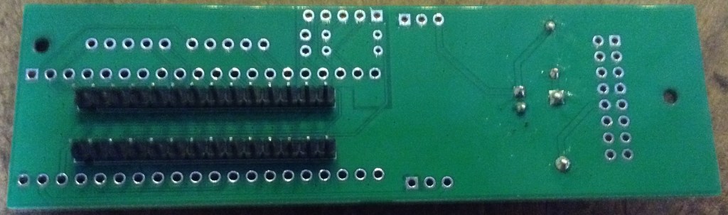
- Interconnecting pin headers (on rear).
- Daisy Seed headers.
- Eurorack power header.
There are a few configuration options, which will be discussed in a moment. For now, here are some build photos.
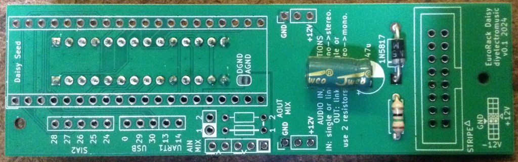
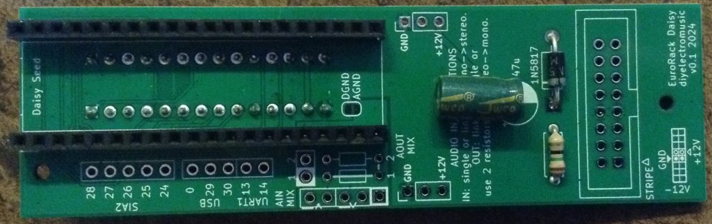
There are a number of configuration options for the audio input and output. I’ll talk through all the options further down, but for this build, I’m assuming all audio will be directed to the plugged-in EuroRack IO board.
This means the following:
- Use headers and install a jumper to connect the two potential audio inputs to the same source (i.e. the IO board).
- Install a wire link for the “AOUT MIX” option, which means that only one audio output channel will be passed directly on to the IO board.
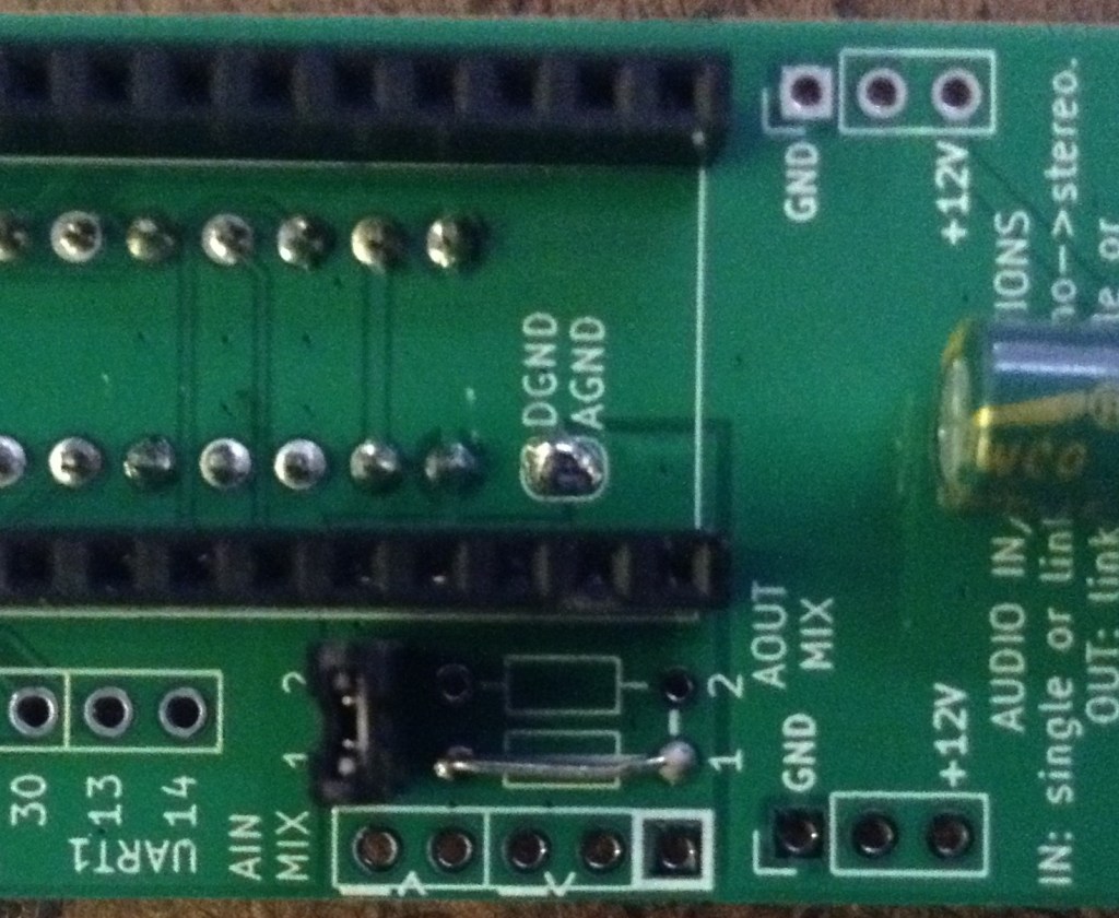
- Connect DGND and AGND by completing the solder jumper.
These are shown below.
Audio Configuration Options
The IO board assumes a mono audio path into the MCU board and back into the IO board. But the Daisy Seed has stereo audio in and out of the board. To allow for the use of stereo if required, I’ve included headers to breakout both audio channels, but also allow for mono operation too.
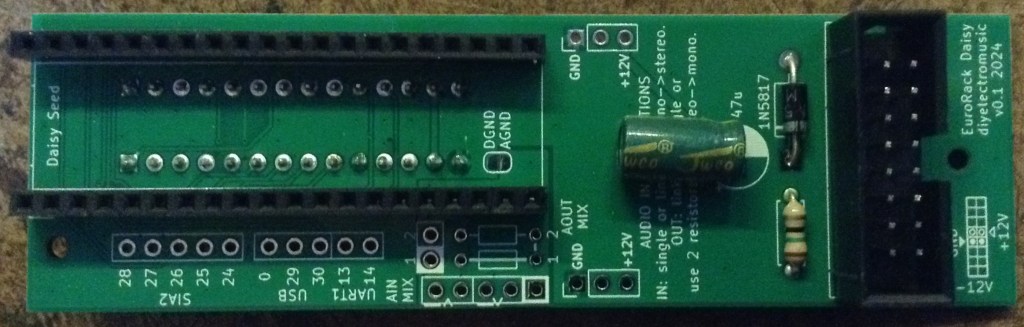
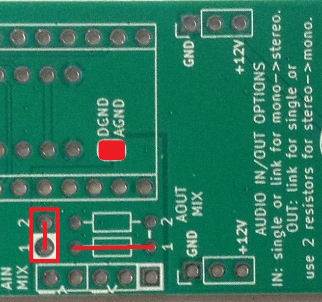
Option 1: Single channel audio IN and OUT via IO board.
This is the configuration I showed earlier. A jumper can be installed which will allow a single mono audio IN from the IO board to go to both Daisy Seed audio inputs. This is just because many of the examples assume a twin audio input.
If the jumper is omitted then a single audio IN channel will be used.
The DGND/AGND solder jumper must be bridged.
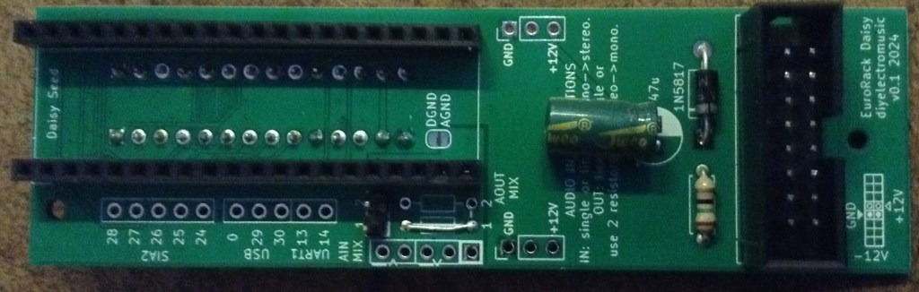
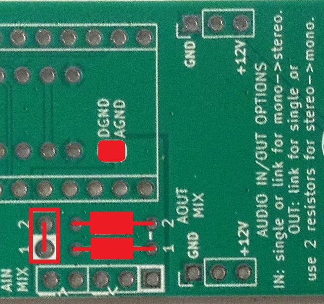
Option 2: Mixed mono audio to IO board from stereo output.
In this option, two resistors are installed in the “AOUT MIX” section which provides a simple passive mixing of the two audio OUT channels into a mono signal that is fed to the IO board.
The input side is as before – a jumper will select whether the single IO board audio IN goes to one or both of the Daisy Seed audio inputs.
Again, the DGND/AGND solder jumper must be bridged.
Option 3: Stereo breakout.
In this option the IO board isn’t used, but both channels for both IN and OUT are routed to a pin header for breaking out elsewhere.
There is a choice about the DGND/AGND solder bridge…
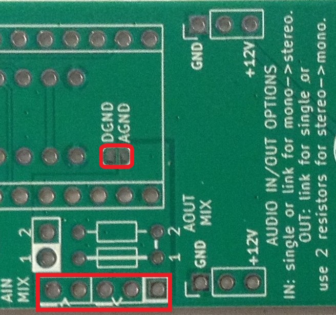
Audio and Digital GND
The Daisy Seed information states that audio and digital GND should be connected for all applications, but I’ve allowed the possibility of keeping them separate by requiring the bridging of a solder jumper to link them together.
This would probably only make sense (to me at least) if following option 3. In this case digital and audio GND really can be considered independent if required.
Testing
I recommend performing the general tests described here: PCBs.
It is strongly recommended that all unused EuroRack power connections are checked and verified that they are unconnected to each other, +12V and GND.
Then it is really down to checking the power supply is working and all of the MCU IO is correctly present on the IO board once it is connected to the IO board.
Please note: None of the IO or audio functions have been tested at this time. I’ll post an update when I get that far.
It is strongly recommended that the board is tested on its own, completely independently of any other modules or an expensive EuroRack power supply. In fact, it is NOT recommended that these boards are used with any other modules or an expensive EuroRack power supply at all. They are designed for use with cheap, DIY systems only.
Usage Notes
Detailed usage notes for use with the IO board can be found here: EuroRack 6HP MCU Experimenter Module Usage Notes.
The Daisy Seed should be fitted on the underside of the board in the orientation as shown below.
Configuration Options – Audio
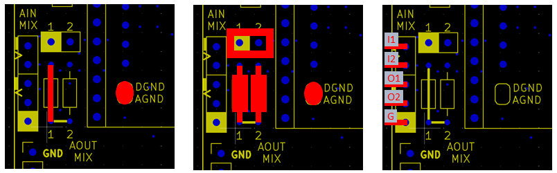
To summarise the three audio options:
- Left: Mono, single channel input and output – Daisy Audio In/Out 1 – routed to the ADC6/ADC7 connectors on the IO board.
- Link wire required.
- No jumper installed.
- DGND and AGND solder bridge required.
- Middle: Mono, merged and mixed dual channel input and output – Daisy Audio In/Out 1 and 2 – routed to the ADC6/ADC7 connectors on the IO board.
- Two resistors required (suggest 1K).
- Jumper (or link) installed.
- DGND and AGND solder bridge required.
- Right: Stereo, dual channel input and output – Daisy Audio In/Out 1 and 2 – routed to the breakout header. ADC6/ADC7 connectors on the IO board are unused.
- No jumper or links or resistors required.
- No DGND/AGND solder bridge required.
- Audio breakout has to be used.
- IO connector ADC6/ADC7 cannot be used.
Note that when the audio is routed to the connector to the IO board that digital GND and analog GND need to be connected via the solder jumper. When the audio breakout is used, the AGND can be kept independent and connected to the Daisy AGND.
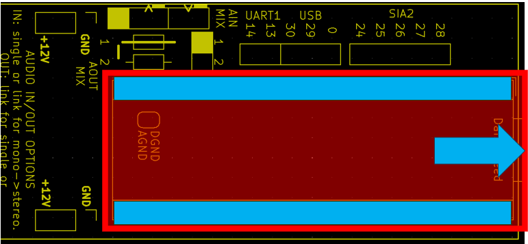
Additional Breakout Headers
Some of the additional Daisy Seed IO is broken out onto additional header pins as shown below.
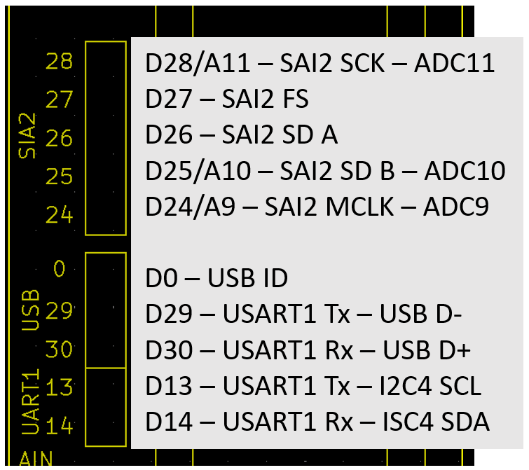
This includes the second hardware serial port (USART1), USB and the second Serial Audio Interface (SAI2).
PCB Errata
There are the following issues with this PCB:
- There is a typo in the labelling of SAI2 – the board says SIA2.
- Also, the UART1 label should really be USART1.
Enhancements:
- None at this stage.
Closing Thoughts
I’ve yet to get back to my Daisy Seed. There are so many example applications online – I really ought to spend some quality time with it!
Maybe this will help.
Just to reiterate, at this time I’ve not tested any of the IO or audio functions. Watch this space.
Kevin
