I’ve seen a number of EuroRack format MiniDexed versions now, from 3D printed panels and designs, right through to commercial modules.
It’s something I’ve been meaning to do for a while, so this is my first attempt at a take on a 8HP EuroRack format MiniDexed using a Raspberry Pi Zero 2 W.
This is a DIY module only for use in my own DIY system.
Do NOT use this alongside expensive modules in an expensive rack. It is highly likely to cause problems with your power supply and could even damage your other modules.
Warning! I strongly recommend using old or second hand equipment for your experiments. I am not responsible for any damage to expensive instruments!
If you are new to single board computers, see the Getting Started pages.
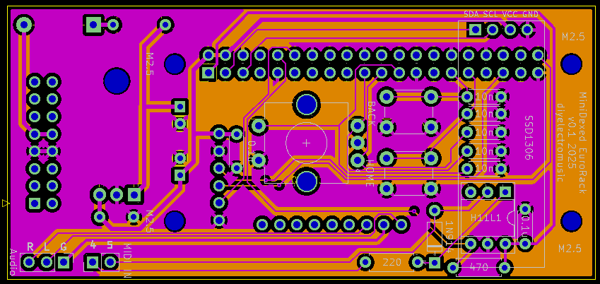
The Circuit
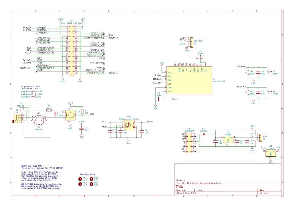
In terms of the circuit, this is essentially my MiniDexed Raspberry Pi IO Board in the SSD1306 format with the EuroRack power supply from my EuroRack 6HP MCU Experimenter Module.
I did toy with the idea of not bothering with a 5V regulator and powering the Pi from the EuroRack 5V line, but I didn’t for a couple of reasons:
- The Pi has no particular protection on its 5V circuit as I understand things, so directly connecting that to the outside world seems like not a good thing to do.
- Using the 12V line and a built-in regulator makes the module more generic in terms of what power it will accept within a EuroRack specified rack system.
- It is easier to protect the 12V/GND setup if a cable is plugged in the wrong way round, than it is for the 5V power lines.
- A fairly inert Pi Zero 2 apparently draws something like 350mA, so it will be quite a drain on a 5V rail, which tend to be spec’d a fair bit lower than the 12V rails. A Pi Zero V1 would have a typical current of around 150mA peaking at ~350mA so that is always an option.
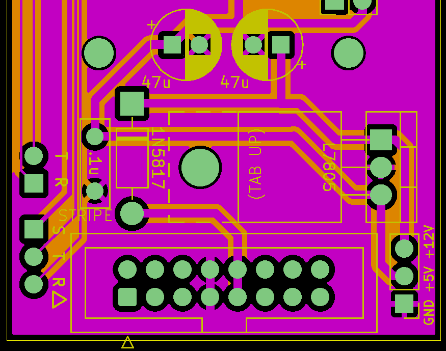
For these reasons I included a 12V to 5V conversion via an L7805 regulator to power the Pi. It does get a bit hot though with a Zero 2, so that has to be taken into account – something I hadn’t done in my first version of this board!
Aside: there are two L7805 regulators shown on the schematic as I’m going to include two footprint options on the PCB itself.
One other thing I’ve left out is the 10Ω resistor. I was largely following comments online when I included it before, but from reading some more (some good discussions here, here and here), I can see that they tend to be included instead of a fuse. But if the Pi is drawing a few 100mA and this is in the 12V input line, then that will be quite a bit of power as I understand things dissipated through that resistor already, so I’ve left it out.
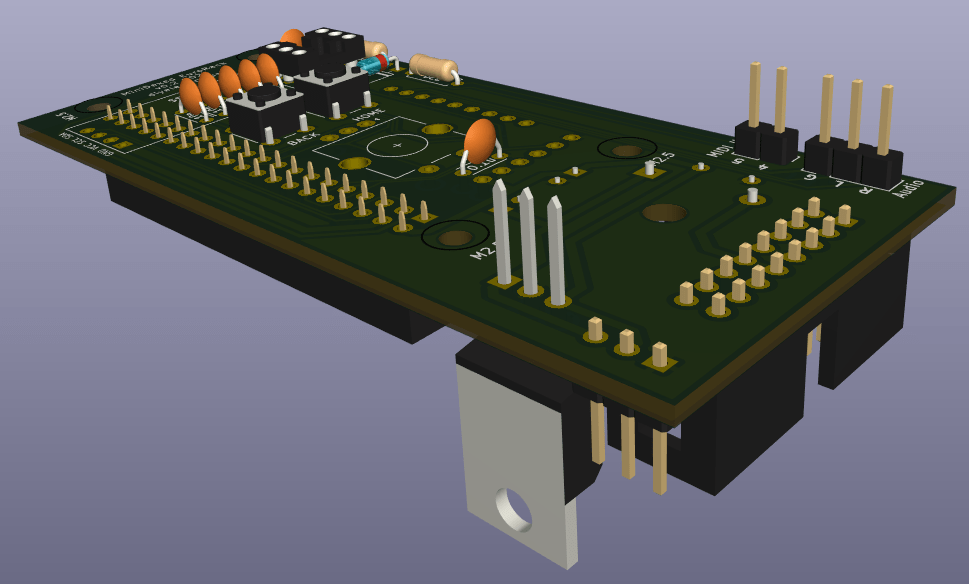
The rest of the circuit is designed around a Raspberry Pi Zero with an I2S audio output via a GY-PCM5102 module, but I’m planning on using headers to link to MIDI IN and audio out on a panel.
I’m not supporting USB MIDI, just serial MIDI. I’m also only supporting MIDI IN.
There are a few components left on the schematic that I’ll be omitting when it comes to putting the PCB together, but I’ve left them there as reminders for the future.
PCB Design
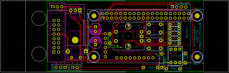
The general idea is to have most of the circuitry on a single PCB that will fit within a 8HP EuroRack module. This means a 40mm (or less) wide PCB and ideally 100mm (or less) long to keep within cheap PCB limits. This works well with EuroRack, leaving 14mm top and bottom for mountings.
I’ve therefore opted for a PCB-mounted encoder, buttons and display and headers linking off to an off-board (still on the panel) MIDI IN socket and Audio OUT. The final PCB is 40x88mm.
Power will come from a EuroRack compatible 16-way connection which will be on the rear of the board. A Pi Zero will also be mounted on the rear of the board.
For expediency I’ve also mounted the GY-PCM5102 on the rear of the board. I’d have quite liked to have made the 3.5mm TRS socket accessible, but I just couldn’t make it all fit. For basic use I was planning on using the L/R/AGND connections anyway to a 3.5mm TRS socket taken to the front panel.
Ideally I’d have used 3.5mm stereo Thonkiconn style connections, but in the end I went for panel-mounted TRS sockets and header connectors instead.
The spacing of the controls isn’t optimum but I was having to compromise with mounting of components and mounting of the encoder and buttons. I think it will be ok, but I’ll have to see when I get it back.
As previously mentioned, not everything on the schematic has been realised on the PCB. I’m going for off-board audio and MIDI jacks, and I’m not bothering with headers for the buttons.
Also, as previously mentioned, I’ve included two footprint options for the L7805 – one vertical and one (tab up) horizontal. The idea is to provide options when it comes to adding a heatsink.
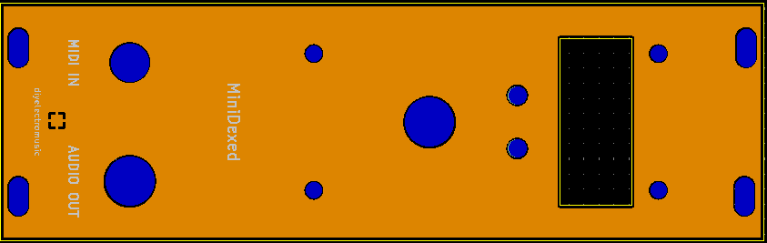
Front Panel
I’ve design a panel to match. This is just using KiCAD to create a PCB panel, as I’ve done before.
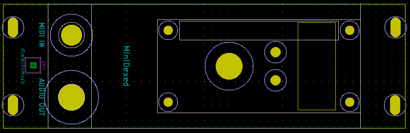
I’ve had to take a bit of a punt with the dimensions of the display. I won’t really know how it will mount until I get all the parts back and try them out.
I’ve taken the mounting holes forward from the Pi through to the panel. Without those, only the encoder would have been keeping the PCB and panel together.
Somewhat annoyingly, I noticed as I was writing this blog post, that I had a stray ref** silkscreen element for the audio jack. When I received the boards back, I had to gently scrape that off with a razor blade.
When I sent off the updated PCB I took the opportunity to also order some more panels with that fixed, but it means I’ll have a choice of either white or black panels when I’m done.
Closing Thoughts
This is something I’ve been wanting to do for some time, so it’s nice to have finally had a look. I kept with the “white look” I’ve been using for my EuroRack experiments so far, but will have a black option too.
The first version had a few issues. First, annoyingly, I managed to get the SSD1306 footprint the wrong way round, so I had a few bodge wires to fix that. And then there were issues with the heat dissipation from the regulator, so all in all, I’ve moved onto a v0.2 of the PCB (unusually for me – I usually just make do :)).
I’m still not convinced about the power situation. Driving a Pi via a L7805 does seem to waste quite a lot of energy, so I need to watch out for the heatsink situation as the build comes together. It might be that directly powering using a USB supply is better, so I might revisit this in the future.
That stray ref is annoying, but that is what you get when you change the size of a hole at the last minute and don’t notice a reference changing layers. So that is just bad luck I guess (unless I really should up my verification process before hitting “send”!).
But then the whole panel was a bit of an experiment as the screen, particularly, was hard to judge up-front without any kind of spatial model, but there seem to be enough options to largely make it work.
So still very much a work in progress, but I think there is a lot of promise, and having a couple of these in a rack does look really neat.
But the general advice still stands – this is a DIY system and should only be used with other DIY modules. If you want a MiniDexed for use in your treasured EuroRack setup alongside your expensive modules, then there are commercial options available, although naturally I have no experience of them myself.
Kevin
