This is an Arduino Uno shield design that can be used to provide up to six clock generator outputs for a sequencer. I’ve built it to use with my Arduino Euclidean Gate Sequencer.
Warning! I strongly recommend using old or second hand equipment for your experiments. I am not responsible for any damage to expensive instruments!
If you are new to Arduino, see the Getting Started pages.
The Circuit
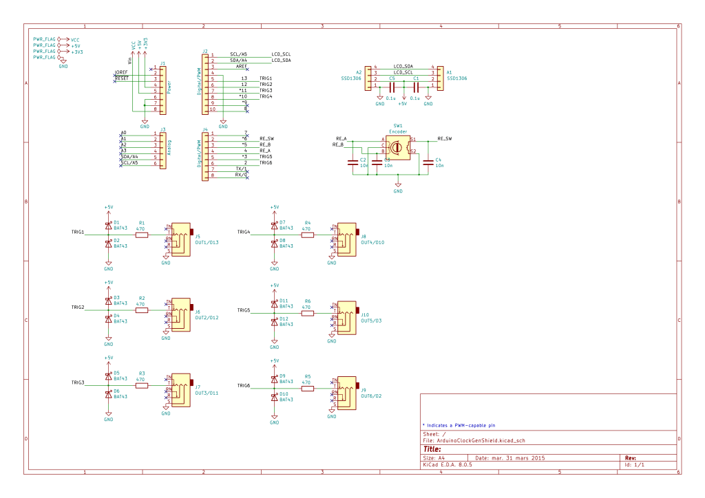
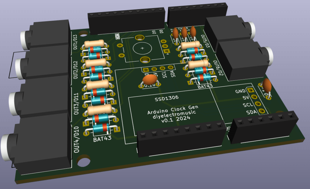
Each output has protection circuitry following the design used by HAGIWO, consisting of clamping diodes and a 470Ω series resistor.
I’ve included a rotary encoder and pinouts for a I2C OLED display.
Note that I’ve used TRS sockets for maximum onwards compatibility, but only the tip and shield are used. The ring is not connected. Hopefully this should mean that the shield would be fine with either mono or stereo cables, depending on what the receiving end requires.
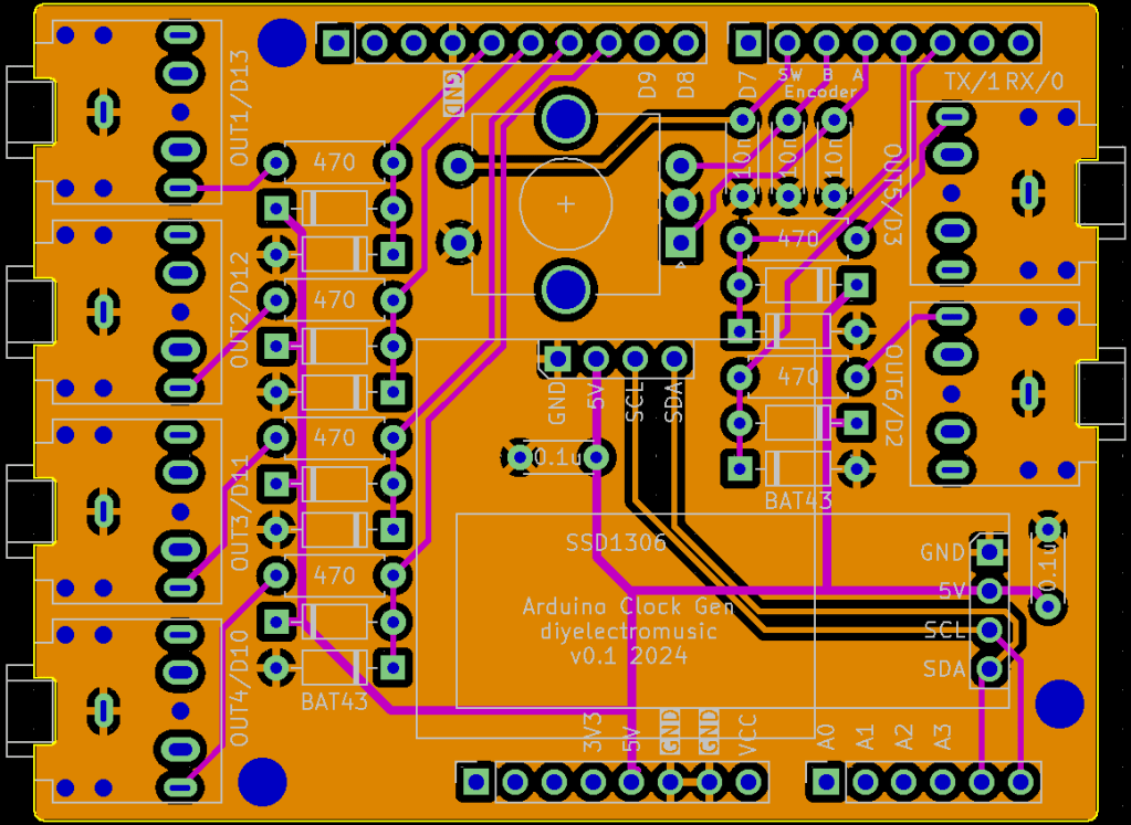
PCB Design
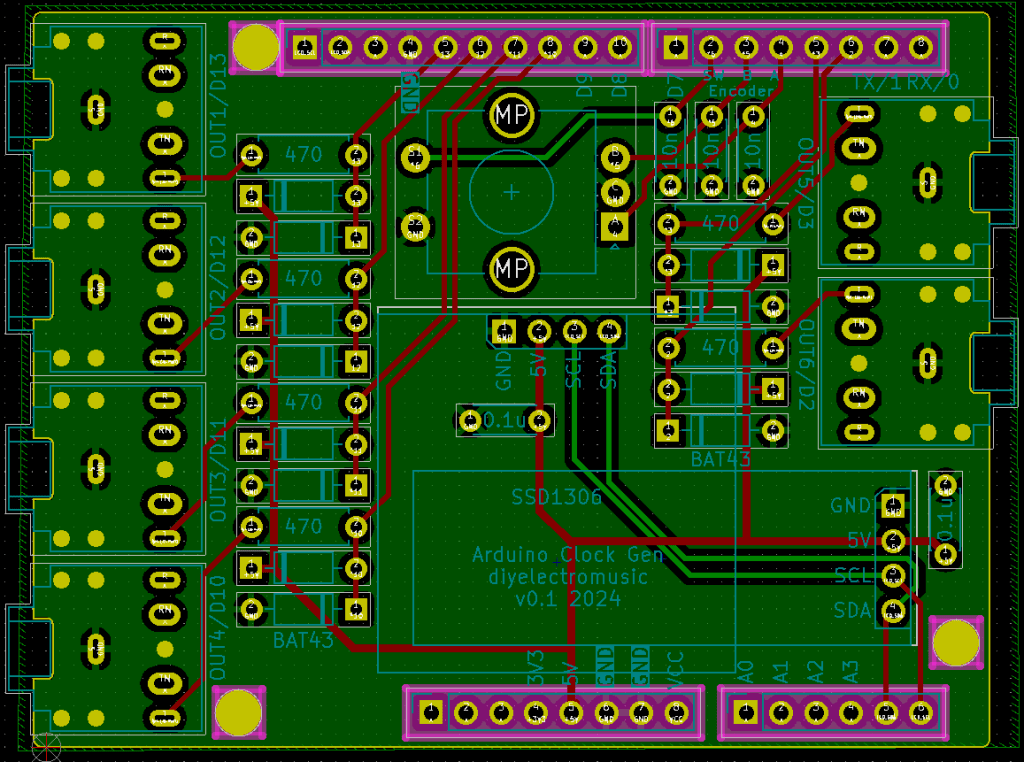
The board started from the Arduino Uno shield template so the board outline, mounting holes and headers were provided as a starting point. I’ve elongated the board slightly and squared it off to support the addition of TRS sockets on each side.
I’ve included two sets of I2C headers to accommodate either a 128×64 or a 128×32 cheap OLED display. Only one set should be populated at a time (although if header sockets are used, naturally both sets of sockets could be present as long as only one is in use).
The design uses a switched encoder.
All unused GPIO pins are labelled. A0-A3, D0, D1, D7, D8, D9 are all free. If no encoder or display is used then naturally D4, D5, D6, A4, A5 will be free too.
The clock outputs have be aligned to the most convenient GPIO pins for routing, but each output is labelled. One of them uses D13 too so the onboard LED can be used as a simple indication of output if required.
Extended headers will have to be used to ensure the solder side of the TRS sockets isn’t shorted out on the Arduino’s USB port or ICSP header.
Closing Thoughts
I wondered about adding built-in LEDS to the PCB but decided I didn’t really have the space. They could be added to the GPIO pins used as clock outputs directly if required.
I wanted the option of essentially using HAGIWO’s code essentially unchanged (apart from pins and display orientation) hence including a footprint for a 128×64 sized display alongside my more usual 128×32 display.
My original code used a potentiometer as a tempo control, but I figured I could use an encoder with some minor adjustments.
With hindsight I am wondering if I should have left the option to use a potentiometer in the encoder’s footprint, but that might have got a bit messy. A future expansion could be the inclusion of an external clock signal.
Kevin
