I’ve wanted to create a non-microcontroller, discrete logic MIDI circuit for some time. I thought it would be interesting to have a few chips that could generate a specific sequence of bytes corresponding to a MIDI message. Note: I’m still talking individual chips here, not just gates and definitely not individual transistors, so perhaps “discrete logic” is a bit of a stretch…
I’ve toyed with various ideas, but not actually properly experimented with anything, but the use of 4017 counters was always there as a possibility.
People have wound up the clocks on a CV step sequencer like these to audio frequencies and created a simple wavetable oscillator.
So seeing as I have a number of “Baby8” CV Step Sequencer PCBs that I’ve just reworked, that will only really work in cascade mode – and seeing as each has 8 switches that control the level of the output GATE signal I thought I would wind the clock up even further and see if I could get it to generate MIDI.
Just don’t ask why.
Warning! I strongly recommend using old or second hand equipment for your experiments. I am not responsible for any damage to expensive instruments!
If you are new to electronics, see the Getting Started pages.
Parts list
- 3x 4017 decade counters.
- 1x 4093 quad NAND gate (or a dual INVERTER of some sort).
- 3x failed “Baby8” CV Step Sequencer PCBs (!) with the following:
- 27x pcb mount SPDT slider switches (2.54mm pitch).
- 24x 1N4018 small signal diodes.
- 12x 100K resistors.
- 3x 100nF capacitors.
- 3x 100pF capacitors.
- 3x 8-way right angle pin headers.
- 3x 8-way right angle pin header sockets.
- 31250Hz clock signal, e.g.:
- 1x NAND gate from the 4093.
- 1x 300R resistor (1% accuracy).
- 1x 33nF capacitor.
- 2x 220R resistors.
- 1x 10K resistor.
- 1x 5 pin MIDI DIN socket.
- Solderless breadboard and jumper wires.
The Circuit
I’m not going to go through the core circuit, as the whole point is to reuse the V1 PCBs from my “Baby8” CV Step Sequencer. I only need to use them as a GATE sequencer – no pitch (CV) or trigger is required, so I can ignore the pots, LEDs, the NAND circuitry, and in most cases the clock too.
I also don’t actually need the rotary switch to select the number of steps – I’m going to be fixing it at 8. I could solder in a clock on one of the boards, but the component values would need changing to give me a steady 31250 Hz clock. I’ve opted to use the same circuit but externally on breadboard to achieve this.
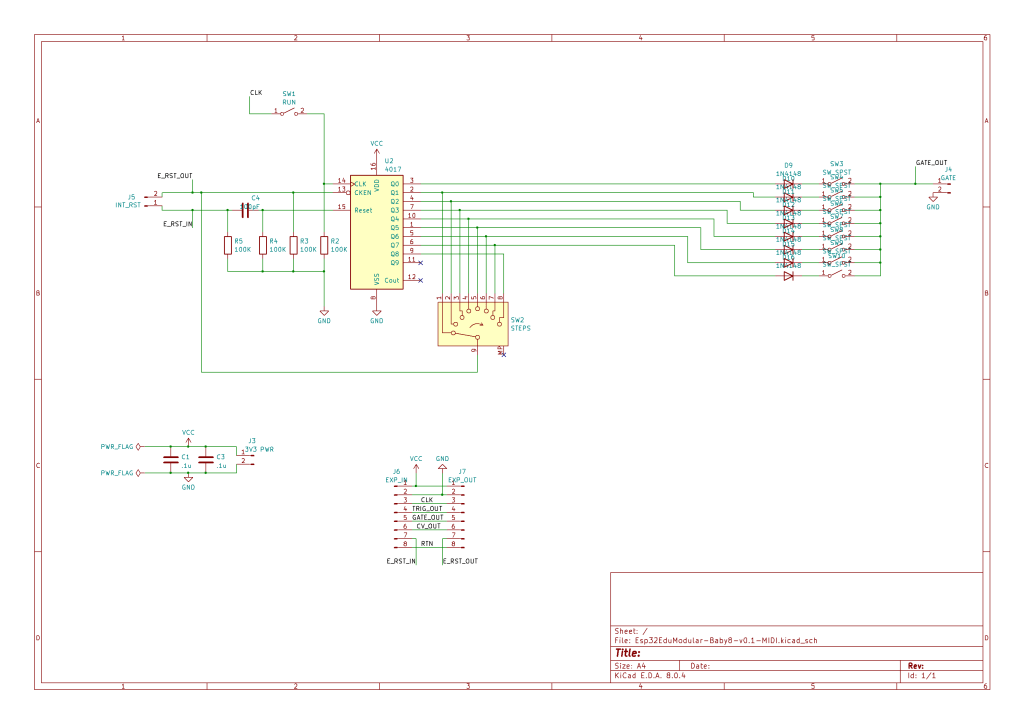
Here is the part of the Baby8 schematic I’m actually using.
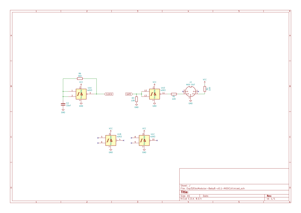
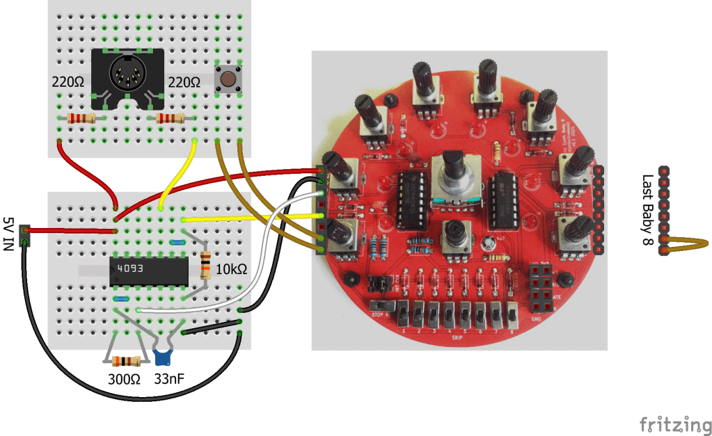
To generate the clock, I put some values in an online Schmitt trigger oscillator calculator and with some trial and error came up with the use of a 330R resistor and 68nF capacitor for my 31,250 Hz oscillator. But in practice it turns out that 300R and 33nF is much better for what I need. I don’t know where the discrepancy lies – my circuit or the calculator, but with these values I have a good enough (for a couple of bytes) MIDI clock.
The MIDI OUT circuit could possibly have been driven directly off the GATE signal but seeing as I have some inverters kicking around (well, actually several NAND gates from my 4093) I thought I’d buffer the signal and then send it to a standard MIDI OUT circuit.
I’ve only used one inverter, so the MIDI signal will be the inverse of the GATE driving it.
During use, I found I had to pull the GATE signal to GND via a 10K resistor to keep it effective, so again that backs up the idea of using a buffer for the MIDI side to me to keep the two parts independent.
Here is the rest of the schematic with the extras I require:
The whole thing is powered directly from a 5A power supply (in my case actually a DIY circuit using a L7805 – a spare from my MIDI Matrix Patch Bay).
Basic Functionality
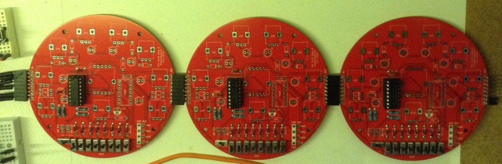
The general idea is to have three of these boards cascaded. MIDI consists of several 8-bit values per message, but each of the 8-bits is also accompanied by a START and STOP bit. This means a typical three-byte message (i.e. most of them) consists of 30 bits and a two-byte message (e.g. Program Change) is 20 bits.
I’ve opted to implement something that can generate two-byte, Program Change messages using the 8 switches on three Baby 8s and hooking that up to the GATE signal. The switches will determine if the signal is HIGH or LOW for that stage in the sequence which will be clocked at the MIDI baud rate of 31,250 Hz.
The Baby 8’s will need to start, cascade through an entire sequence of 24 steps (to cover the required 20 bits), and then stop. To do this I’m going to use the “RST return” feature of my PCBs and the RUN switch on the first Baby 8.
Once everything is wired up to the external clock and MIDI OUT circuit, the basic sequence will be as follows. Note I have to power OFF if this is the first use to ensure everything starts in the right place. Further uses do not require a power cycle.
- Set RUN to STOP on the first Baby 8. It will always be left on RUN on the other two.
- Power ON if this is the first use.
- Set the byte values to be sent via the switches.
- Press the RESET button which temporarily completes the RST chain and ensures the sequencer cycles round to the first step, outputs that GATE value which it will hold and then halts.
- Set RUN to RUN which then runs through all 24 steps setting the GATE level according to the switch settings.
- Repeat sequence from the beginning to send further messages.
Assembly and Build
I don’t need to build complete Baby 8 boards – as already indicated I only really want the counter and GATE outputs. These are the sections of the V1 PCB I need to be populated:
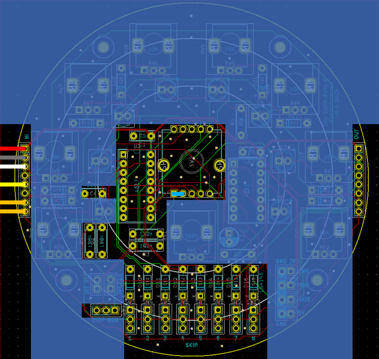
As I’m not using the rotary switch, and all the components I’m adding still leave me the option of populating the rest of the components at some point in the future to restore the full (albeit with issues) “Baby 8” functionality, I’ve used the “fishing line trick” to add a non-soldered link between the switch’s step #8 and the return (as indicated in cyan above).
Note that a jumper is required on the last Baby 8 to route the RST signal back through the boards to connect to a manual RESET switch.
Generating MIDI from Discrete Logic
In order to produce a MIDI Program Change message, the following sequence of bytes is required.
MIDI Msg = CMD + DATA
0xCn 0xdd
  !!   ++--- 7 bit data byte for program number (1..128 = 0x00..0x7F)
  !+-------- MIDI channel (1..16 = 0x0..0xF)
  +--------- MIDI Program Change command (0xC)
So for MIDI channel 1, the sequence, including START (S) and STOP (E) bits, will be as follows. Note MIDI has the least significant bit sent first, just after the START bit, so reading from left to right is the sequence in which the bits are sent too – time flows to the right (just like an oscilloscope trace).
0xC0 0x04  -> Program Change to voice 5

0 0000 0011 1 0 0010 0000 1
S  Ch1   PC E S  Data=4   E
This requires the switches set as follows:
HLLL LLLL HHHL LLLH LLLH HHHH
                       +------- STOP and remain HIGH to finish
               ++++-+++-------- 7 bits of data to encode 0x04
             +----------------- START
            +------------------ STOP
       ++ ++------------------- 4 bit command 0011 = 0xC (PC)
  ++ ++------------------------ 4 bit channel 0000 = 0x0 (Ch 1)
 +----------------------------- START
+------------------------------ Preamble starts HIGH
Due to the use of the inverter as a MIDI OUT buffer, a H is generated from the GATE being LOW – i.e. having a step skipped (switch down).
In order to ensure I get a good START bit, the first switch (which is the “hold” step until the RUN is started) is set to generate and therefore hold a H level.
The program number to be set is chosen by encoding a number between 0 and 127 (corresponding to programs 1 to 128) backwards (the step sequence is also left to right) on the appropriate 7 switches – four on the second Baby 8 and three on the last.
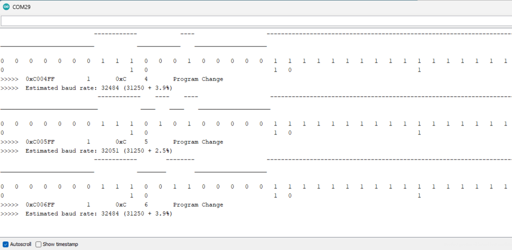
Here are some traces of the boards in action. Both traces show selecting voice 5 (sending byte 0x04 as data).
The first is a trace from my Arduino MIDI Logic Analyser, which also gives an estimate of the baud rate in use. I had to modify it slightly to cope with two-byte messages – it was only dealing with three-byte messages before. I’ll update the code and message handling one day.
We can see that the baud rate is still a little high compared to what is required, but it seems close enough for just a two-byte message.
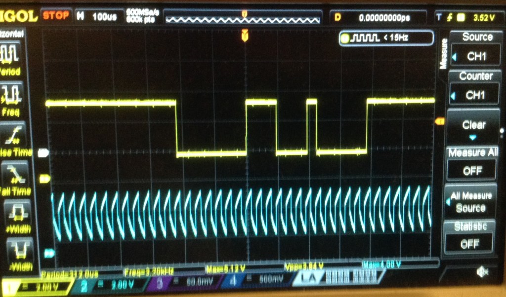
And here is an oscilloscope trace of the clock signal (blue) and the MIDI OUT signal (yellow) for the same message.
The first drop is the START bit. The two highs are the end of the PC byte and the STOP bit. Then there is another START bit and then binary 0010 – which is 4 when encoded LSbit first (on the left) followed by more zeros until the final high STOP bit and a few trailing highs.
Conclusion
I’ve wanted to do something like this for a while now so actually really quite enjoyed this somewhat pointless activity. Of course, using PCBs like these is massive overkill and the utility of the result is very questionable.
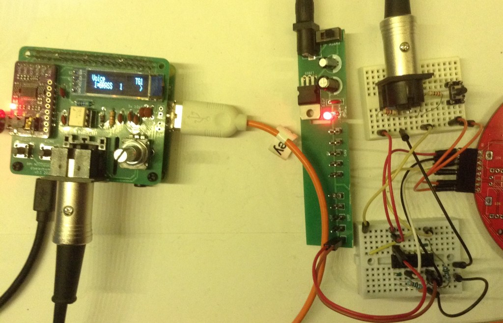
The video shows me selecting different patches on a MiniDexed. You can just about see the voice name change on the display, but hopefully you hear the difference going from Brass 1 to Strings 1, Strings 3, Strings 2 and back to Brass 1 again.
But the V1 PCBs were sitting on my bench, and for the sake of soldering on a few cheap components provided an easy way to test the idea.
And I’ve not soldered anything on that means I couldn’t turn these back into full (but limited) Baby 8 sequencers if I wanted.
So I’d say this is a win. But as I say, just don’t ask me why.
Kevin