A common early project for anyone starting to play around with analog synthesis is a “Baby8” step sequencer. There are many designs out there on the Internet and many ready-designed kits that can be bought and made. I can recommend the Rakit Baby8, which has some neat features. I’ve used it with my Educational Synth Thing.
- Part 1 – This post with the introductory design information.
- Part 2 – The design for a PCB based on the principles in the first post.
- Part 3 – The build and test notes for the PCB.
- Part 4 – Usage notes for the PCB and how to use it with the Educational Synth Thing.
This is a first look into how they work with a view to reinventing this wheel and eventually making my own.
Warning! I strongly recommend using old or second hand equipment for your experiments. I am not responsible for any damage to expensive instruments!
Here are some existing articles that detail the main concepts used in this project:
- Eddy Bergman’s 8-step sequencer.
- B8BY Baby 8 step sequencer.
- Benjaio Modular 8-step sequencer.
- Hackaday Baby10 sequencer.
- DIY Audio Circuits CMOS 4017 Based 8 Step Sequencer.
- Look Mum No Computer’s Arduino 8-step sequencer and a discussion about different circuits.
- A Euro-rack format Baby 8.
If you are new to Arduino, see the Getting Started pages.
Introduction
The basis of the Baby 8, at least all those that haven’t been reimplemented using a microcontroller, is the CD4017 decade counter chip. This has 10 outputs and each will be set HIGH in turn on reception of a trigger pulse, which makes this a very simple way of triggering different output steps, in sequence, one at a time, in response to some kind of pulsed or clock input.
There is also a octal counter, the CD4022, with 8 outputs but for some reason, everyone seems to use the 4017 even though most builds only use 8 steps.
I won’t go into the details of using the CD4017 as this Hackaday article provides a great introduction already, but I’ll summarise as follows:
- Each of the outputs can be fed into a potentiometer which then allows each step to have a configurable voltage between 0 and VCC.
- One of the outputs is also linked to the CD4017 RST pin which then resets the sequence. By having this configurable, different length sequences (up to 10) can be set.
- Some circuits assume an external clock signal; some include an internal clock.
- The internal clock signal often comes from a 555 timer or a simple inverter-based oscillator, each with a configurable frequency.
- Output is the variable voltage from the potentiometers, which have to be summed together at the output.
- A gate/trigger style output is required at the start of each sequence step, usually triggered off the same clock input.
- Most designs include an LED for each step.
Some additional extras I’ve seen in some builds include:
- A stop switch to pause the sequence.
- Mute or skip switches to inhibit specific steps.
- Single step or hold functions.
- An LED for the clock.
- A configurable pitch (voltage) offset for the outputs.
- A configurable duty cycle for the gate (clock).
The key features I want are as follows:
- 0-3V3 CV and either 3V3 or 5V gate, for use with my Educational Synth Thing.
- Internal clock generation, no need for an external clock input.
- LEDs per step.
- Powered by 3V3 or 5V (to be decided).
- Optional: 9V power supply.
- Optional: buffered CV/gate jack outputs.
Ideally I’d like the 8 steps arranged in a circle, but that is to be decided too. I’m not sure if I’ll include the optional items, as there are already pretty well featured DIY kits available. I’ll probably just work on what I need for use with my educational synth thing.
I would like to include mute switches and some way to configure the number of steps in the sequence.
The other thing I’d really like to have done is to use “clear shaft” potentiometers, like those used on the Korg Volcas, but these seem pretty hard to find. Taiwan-based Alpha appear to do some, but they are quite costly and not easily available in the UK (without the minimum buys and high postage costs from a large professional distributor).
In the end, I decide to stick with normal pots and separate LEDs.
A note on clocks.
As already mentioned an internal clock source is often provided and these generally seem to be one of a couple of types from what I’ve seen.
The 555 timer is one option. The circuit will configure the 555 in astable, multivibrator mode which generates a square wave signal with the period (frequency) dependent on the components used. There are many tutorials online that talk about how to do this.
I’ll link to Mitch Electronics here as they provide a neat little kit for experimenting with them on their own, but I’ve also looked at these myself here: Simple Square Wave Oscillator PCB Design.
Other circuits use a schmitt trigger inverter oscillator circuit, or sometimes a NAND gate equivalent. There is a good discussion of how this works and some design considerations here:
- All About Circuits – Exactly how Schmitt Trigger Oscillators Work.
- All About Circuits – How to Design Schmitt Trigger Oscillators.
The last article contrasts the use of inverters vs NAND gates and also discusses some of the issues relating to using TTL or CMOS logic for this purpose.
In terms of options for actual devices, I’ve picked out the following to consider:
- CD40106 – CMOS hex Schmitt Trigger inverter. VCC=3-18V.
- 74HC14 – CMOS hex Schmitt Trigger inverter. VCC=2-6V.
- 74HCT14 – as above but supporting TTL loads. VCC=4.5-5.5V.
- CD4093 – CMOS quad Schmitt Trigger NAND. VCC=3-18V.
- 74HC00/74HC20 – single/dual Schmitt Trigger NAND. VCC=2-6V.
and so on.
The only major consideration for me is that if I can support it being powered from a 3V3 supply then that would mean that the default output will be in the neat 0-3V3 range I’d like for my educational synth. Essentially any of these would do that apart from the HCT variants of the devices.
This is the proposed circuit, using a NAND gate as an inverter. I’ll be using more NAND gates later too, so using a NAND here makes sense even if only used as an inverter.
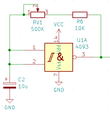
As this will be powered from the 3V3 supply, I did some testing with different values for the capacitor and resistor and found the following frequency ranges:
| 0 | 10K | 100K | 500K | |
| 2uF | 300Hz | 33Hz | 3Hz | 0.6Hz |
| 3.3uF | 240Hz | 24Hz | 2.5Hz | 0.4Hz |
| 4.7uF | 160Hz | 16Hz | 1.6Hz | 0.3Hz |
| 10uF | 70Hz | 7.5Hz | 0.7Hz | 0.2Hz |
As this is the step controller for a sequencer, I went with a 4.7uF capacitor and 500K potentiometer, however I did find that with no resistance the square wave essentially becomes a triangle wave, so I’ve also added a fixed 10K resistor to give a resistor range from 10K-510K which ensures that the square wave is always fairly well defined.
In the end this gives me a frequency range of around 0.3Hz to 16Hz, or thereabouts. This is equivalent to between 20 and 960 steps a minute, give or take.
Cascading 4017 Counters
As the key idea with a looping 4017 counter is to use one of the outputs to reset the counter, it is actually possible to link several counters together and get them to reset each other. The key trick is to make use of the CLK inhibit (CI) pin. When this is high it stops the clock, so this can be used to ensure that a counter is only counting when it is it’s turn.
There is a detailed discussion of the ideas here: https://electro-music.com/forum/topic-63068.html In particular a number of the circuits posted by Phobos (one of which is also referenced by Kristian Blasol in his “Modular in a Week” video series here) work through the core idea.
The final suggested design is as follows:
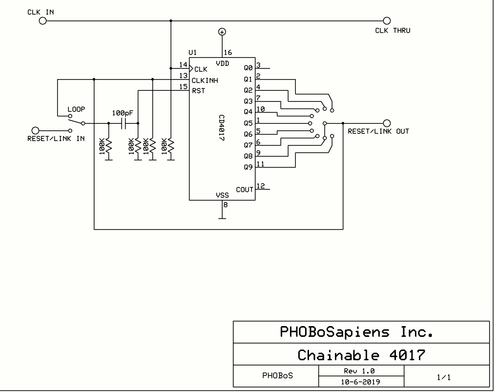
The key principle here is that the CLKINH line has to be LOW for the counter to run. This is tied to the last output in the sequence, so when that goes HIGH one of two things could happen:
- Without any chaining, i.e. for a single counter, this output is tied to the RST signal, so when it goes HIGH CLKINH also goes HIGH and stops the counter, but also RST temporarily goes HIGH too, which resets everything, including clearing the last output and thus resetting CLKINH back to LOW.
- With chaining, i.e. with two counters linked as indicted above, then CLKINH goes HIGH which stops the counter and will remain HIGH until it gets RST. In this case that will only come from a chained 4017 further down the line.
Note: each of these signals is pulled LOW by default via a 100K resistor, and there is a 100pF capacitor in the RST line to ensure it only gets pulsed rather than staying HIGH.
What would be ideal for me is to have a way to break out the various signals required to cascade counters via a jumper header to allow units to be plugged into each other. Something to think about.
Parts list
- 1x CD4093 Schmitt trigger quad NAND
- 2x CD4017 decade counter
- 16x LEDs
- 16x 220Ω resistors
- 1x 10KΩ resistor
- 2x 100KΩ resistors
- 1x 500KΩ potentiometer
- 1x 4.7uF electrolytic capacitor
- 2x 100pF ceramic capacitors
- Breadboard and jumper wires
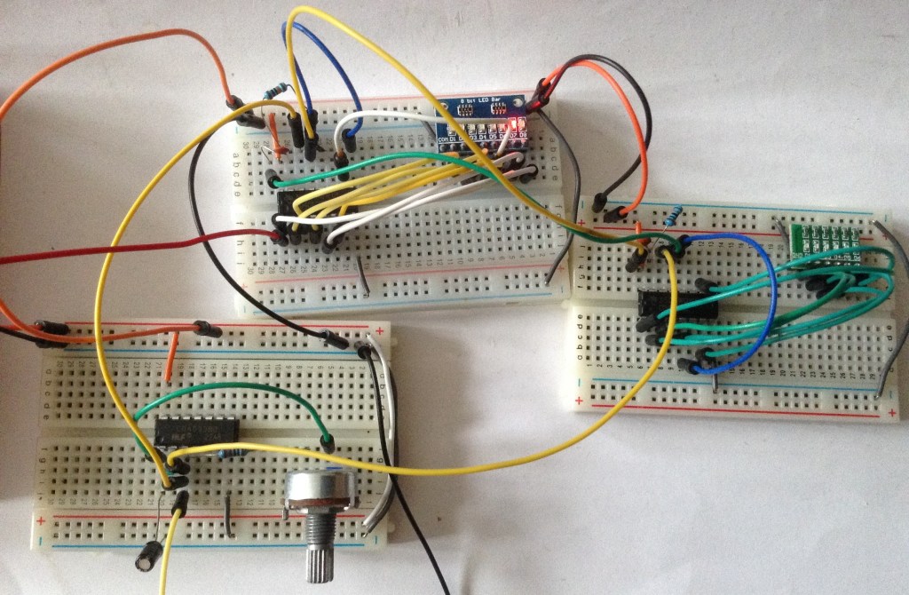
The Circuit
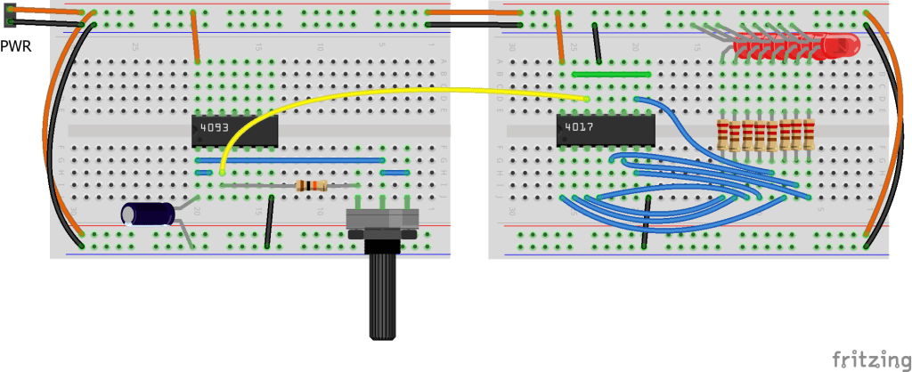
The core oscillator and counter circuit is shown above. This will run the counter at a frequency set by the potentiometer and cycle through the display of all 8 LEDs. The circuit can be powered by 3V3 or 5V.
The following shows how the circuit can be expanded with a single cascade to a second 4017 counter.
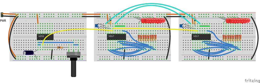
The oscillator section is the same but the clock output is now connected to the clock input for both 4017s. As described earlier, the Q8 output of one 4017 is connected to both its own CI pin and the other counter’s RESET pin (via the 100pF capacitor).
To turn this into a Baby 8 sequencer requires the use of a potentiometer on the output of each of the 4017’s counters and some means of generating a GATE signal.
But at this stage, I’m going no further with the solderless breadboard implementation and switching over to a PCB, which I’ll describe in my next post.
Closing Thoughts
It has been really interesting to work through the use of a NAND oscillator and how it can drive cascading 4017 timers. The video at the start shows them in action, although I only had an 8-way and 6-way LED block to use, so I stopped the second one after 6 steps.
The next part will consider how to generate control voltages for pitch alongside a GATE signal to trigger an actual note.
Kevin

@diyelectromusic.com couple of variants with the 4040 / 4051 (my faves for sequencing): with envelopes: https://electro-music.com/forum/viewtopic.php?t=72807
very flexible: https://hackaday.com/2015/02/23/logic-noise-the-switching-sequencer/
A very reduced version of the casper electronics classic 4040 design https://blog.adafruit.com/2017/08/21/voltage-sequencer-for-moog-mother-32-made-from-4040-counter-4051-multiplexer-and-a-40106-oscillator/
LikeLike
Remote Reply
Original Comment URL
Your Profile
Why do I need to enter my profile?
This site is part of the ⁂ open social web, a network of interconnected social platforms (like Mastodon, Pixelfed, Friendica, and others). Unlike centralized social media, your account lives on a platform of your choice, and you can interact with people across different platforms.
By entering your profile, we can send you to your account where you can complete this action.
Great thanks – I’ll take a look 🙂
LikeLike