Here are the build notes for the MiniDexed Quad DAC PCB.
Warning! I strongly recommend using old or second hand equipment for your experiments. I am not responsible for any damage to expensive instruments!
If you are new to single board computers, see the Getting Started pages.
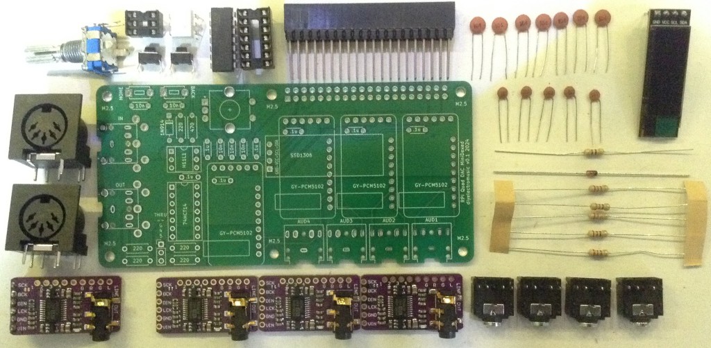
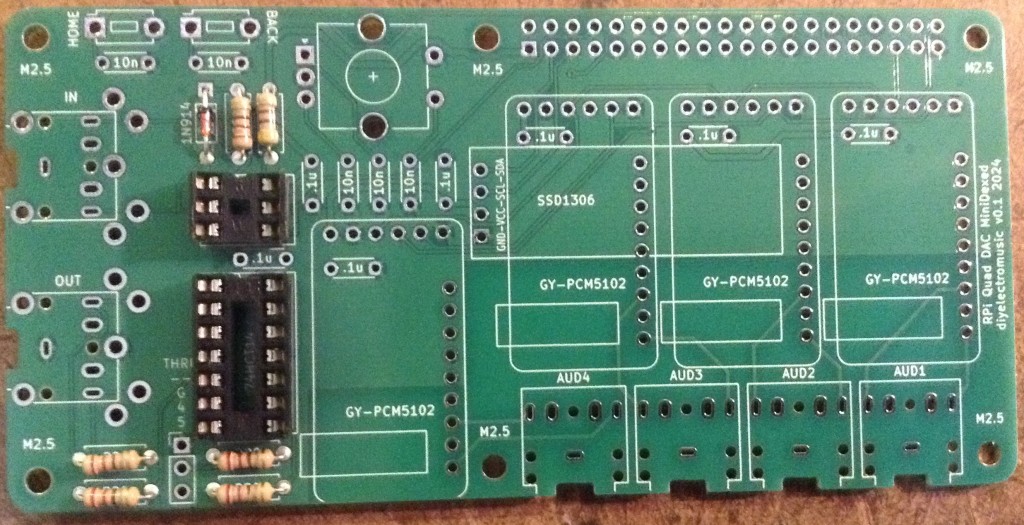
Bill of Materials
- MiniDexed Quad DAC PCB (GitHub link below).
- 4x GY-PCM5102 modules.
- 1x SSD1306 OLED 32×128 display (GND-VCC-SDA-SCL pinout).
- 1x 74HCT14 schmidt trigger inverter.
- 1x H11L1 optoisolator.
- 1x 1N914 or 1N4148 signal diode.
- 5x 220Ω resistors
- 1x 470Ω resistors
- 5x 10nF ceramic capacitors.
- 7x 100nF ceramic capacitors.
- 4x 3.5mm pcb mount stereo TRS sockets (see photos for footprint).
- Either: 2x 3.5mm pcb mount stereo TRS sockets or 2x 5 pin 180 DIN sockets.
- 2x 2-pin tactile buttons (see photos for footprint).
- 1x switched rotary encoder.
- 1x 2×20-way extended GPIO header socket.
- Optional: 1x 6-way DIP socket; 1x 14-way DIP socket.
Build Steps
Taking a typical “low to high” soldering approach, this is the suggested order of assembly:
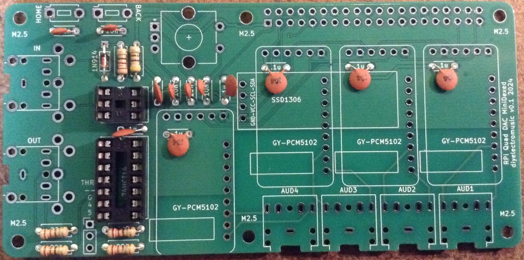
- All resistors and diode.
- DIP sockets (if used).
- Disc capacitors.
- TRS sockets.
- Buttons.
- GY-PCM5102 modules.
- THRU header pins (if used).
- GPIO socket.
- DIN sockets (if used).
- Rotary encoder.
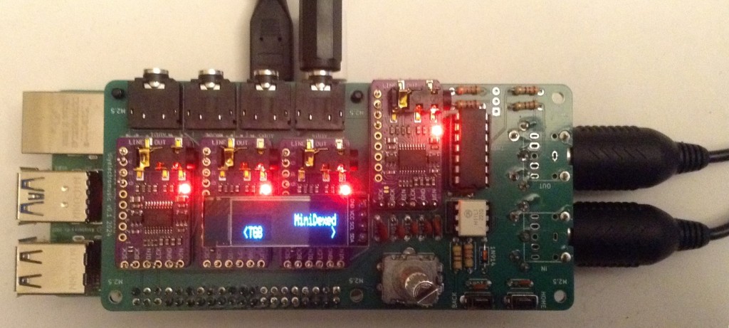
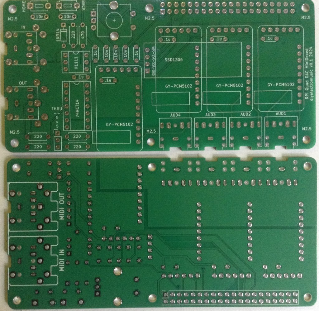
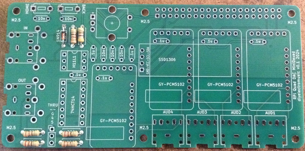
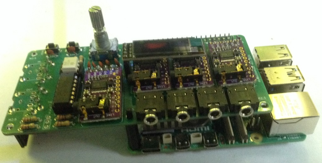
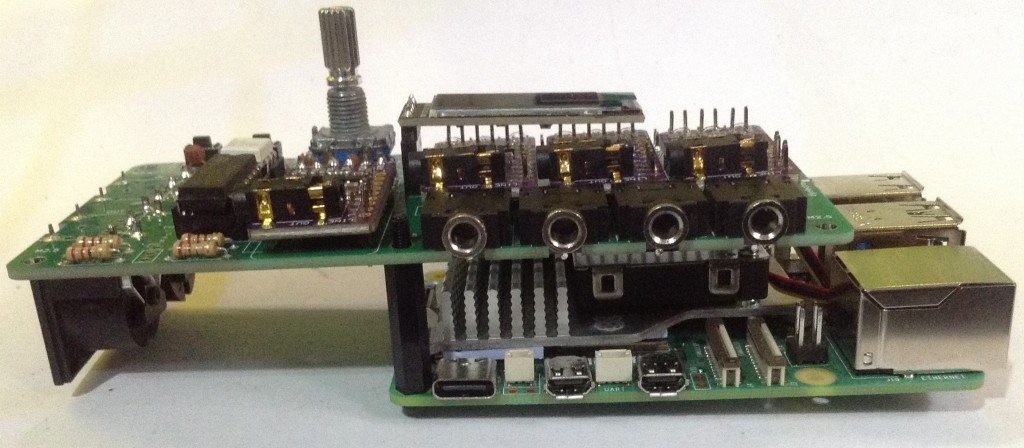
Here are some build photos.
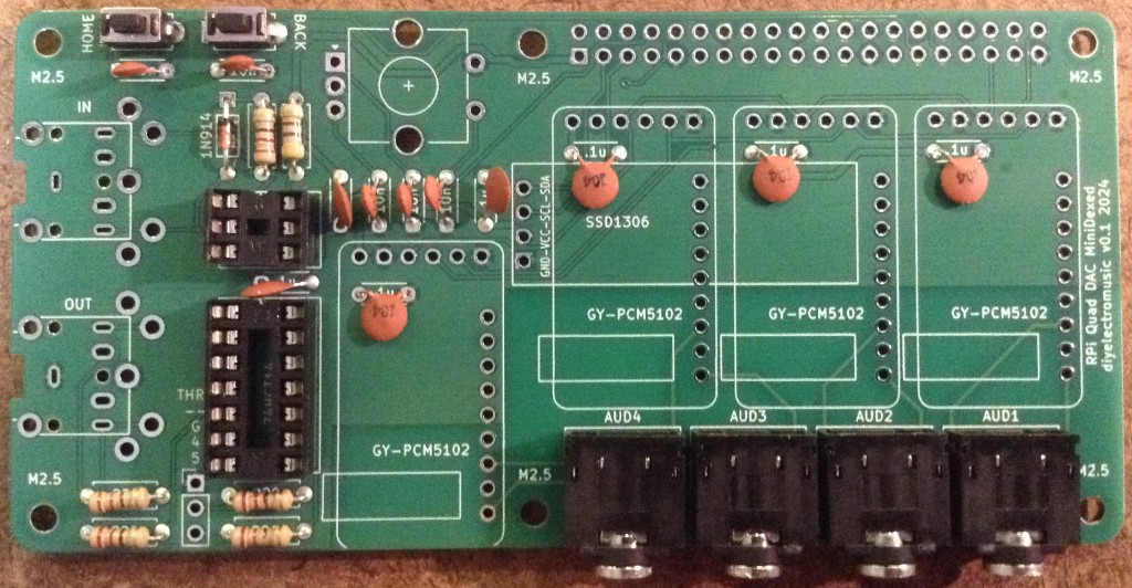
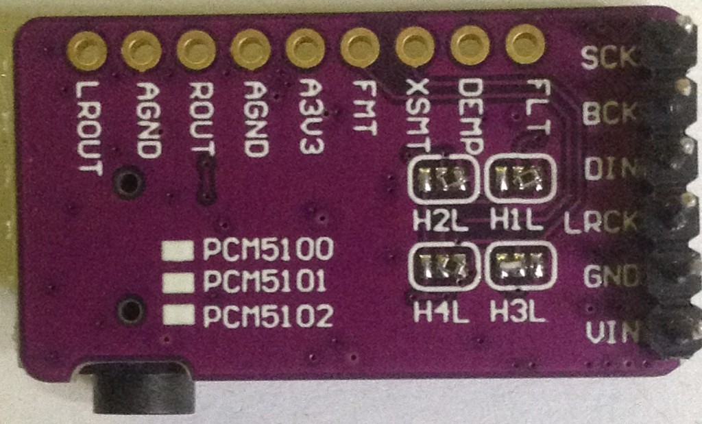
Note: the PCM5102 modules must have the solder jumpers set prior to soldering onto the PCB. Some modules come with solder jumpers set, some with 0Ω resistors and some requiring soldering. The correct configuration is as shown below: 1L, 2L, 3H, 4L.
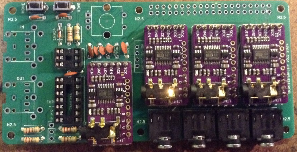
Note: I’ve not actually soldered on the PCM5102 modules, as I didn’t want to commit four modules just to this PCB. Instead, I’ve used the “fishing line trick” to secure them onto header pins without soldering (more here).
I’ve used an extended GPIO header socket and have extended it even further using the spacers from some pin headers as shown below.
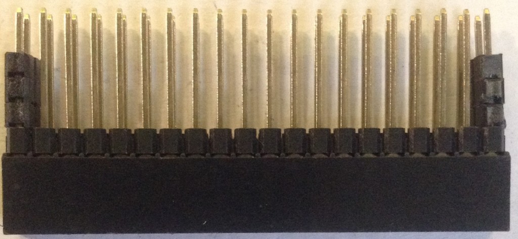
This is to ensure there is plenty of space above the heatsink of the Raspberry Pi 5.
I’ve also used a 4-way header socket for the OLED display which serves two purposes – it means I can replace the display if I mess it up; but it also raises the display above the PCM5102 modules.
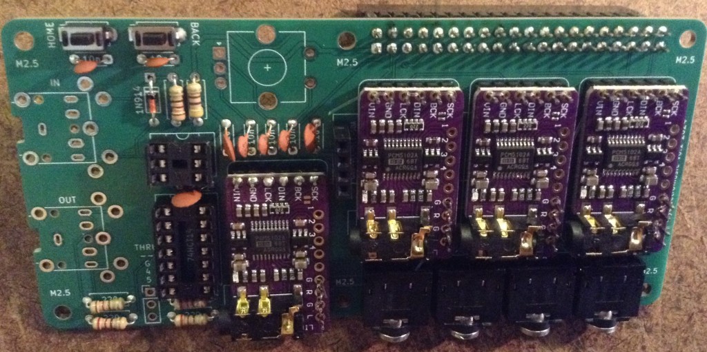
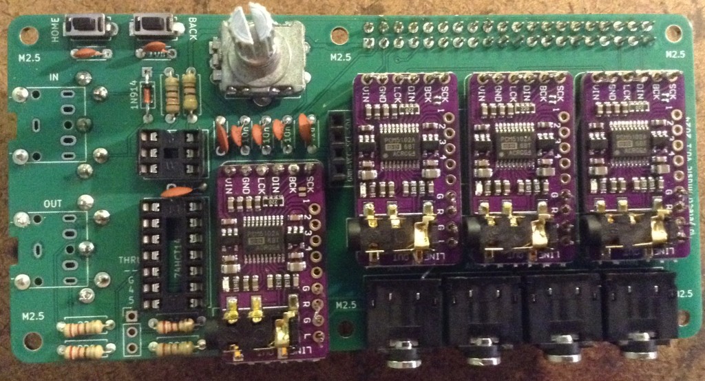
The completed board is shown below and in the first photo in this post.
Testing
I recommend performing the general tests described here: PCBs. In particular it is strongly recommended to check for shorts between 5V and GND and 3V3 and GND prior to connecting to a Raspberry Pi 5.
PCB Errata
There are no issues known at present.
Enhancements:
- The physical layout of the board could perhaps have extended over the USB sockets, given the size of the spacers that were eventually used. This means it wouldn’t extend quite so far off to the side of the RPi.
- I did wonder about attempting to use 8x mono audio sockets, but instead opted for 4x stereo sockets for physical layout reasons.
- I really should have labelled MIDI IN/OUT on the top of the board 🙂
MiniDexed Configuration
To use this with MiniDexed requires Raspberry Pi 5 quad-DAC support (hopefully to be integrated in the main code soon – it is a PR at the time of writing).
The following configuration options in minidexed.ini are the significant ones required for this board:
SoundDevice=i2s
QuadDAC8Chan=1

LCDEnabled=1
SSD1306LCDI2CAddress=0x3C
SSD1306LCDWidth=128
SSD1306LCDHeight=32
SSD1306LCDRotate=1
SSD1306LCDMirror=0

LCDColumns=20
LCDRows=2

ButtonPinPrev=0
ButtonActionPrev=
ButtonPinNext=0
ButtonActionNext=
ButtonPinBack=5
ButtonActionBack=click
ButtonPinSelect=11
ButtonActionSelect=click
ButtonPinHome=6
ButtonActionHome=click

EncoderEnabled=1
EncoderPinClock=10
EncoderPinData=9
Note that any performance settings for pan or effects are ignored when used in 8-channel audio output mode, and each tone generator is assigned a single audio output channel as follows:
- TG 1: Audio Out 1 Left
- TG 2: Audio Out 1 Right
- TG 3: Audio Out 2 Left
- TG 4: Audio Out 2 Right
- TG 5: Audio Out 3 Left
- TG 6: Audio Out 3 Right
- TG 7: Audio Out 4 Left
- TG 8: Audio Out 4 Right
Closing Thoughts
I must admit that I’m not sure if I’ll ever use this myself, but I had to take a look once the possibility had presented itself. This is the main reason I haven’t actually soldered on the four GY-PCM5102 modules myself.
But this does seem to work pretty well from my experiments so far.
Of course, it is probably a lot easier to buy a HiFiBerry dac8x board if you can get one 🙂
Kevin

One thought on “MiniDexed Quad DAC PCB Build Guide”