Here are the build notes for my Simple Square Wave Oscillator PCB.
Warning! I strongly recommend using old or second hand equipment for your experiments. I am not responsible for any damage to expensive instruments!
If you are new to electronics, see the Getting Started pages.
Bill of Materials
Oscillator components:
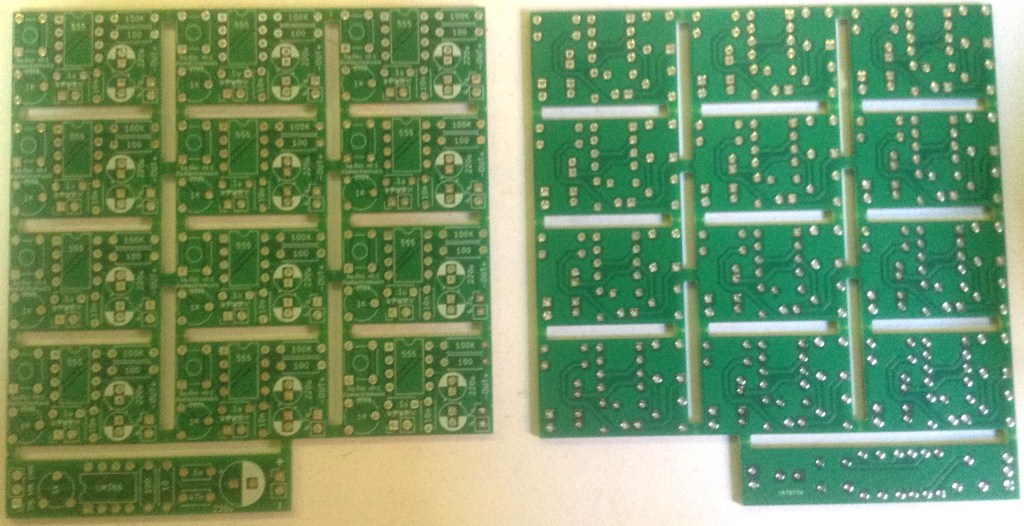
- Simple Square Wave Oscillator PCB (GitHub link below).
- 555 Timer.
- Optional: 8-pin DIP socket.
- 100Ω resistor.
- 100K resistor.
- 1KΩ trim potentiometer.
- 10nF ceramic capacitor.
- 100nF ceramic capacitor.
- 4.7uF electrolytic capacitor.
- 220uF electrolytic capacitor.
- Tactile button switch.
- Optional: pin headers.
- 9V battery clip.
- Old (30-40Ω recommended) headphone speaker.
- Optional: additional current-limiting resistor for speaker (see design notes).
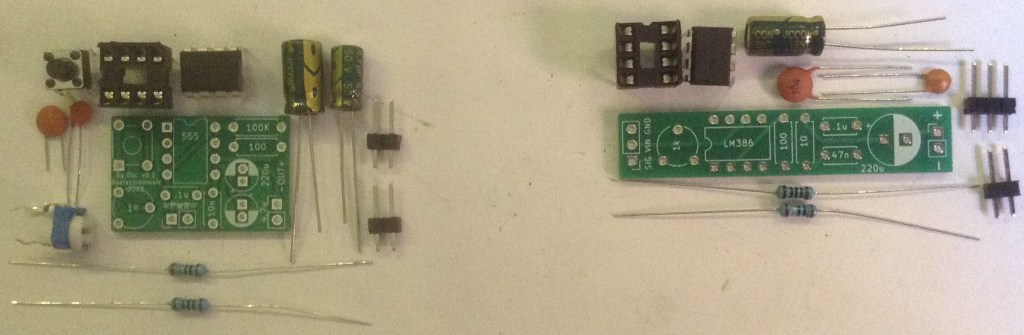
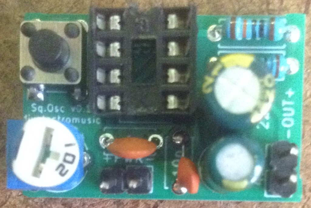
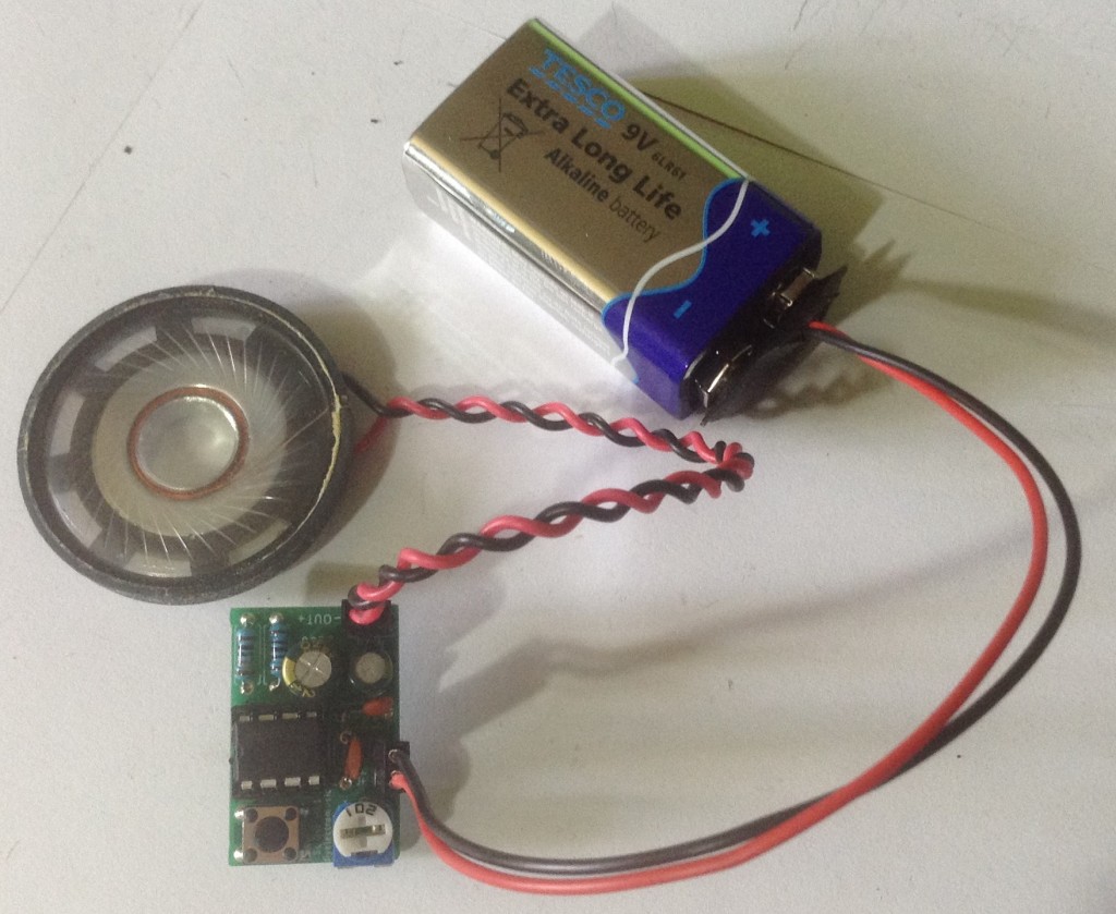
I’ve not detailed how to build the amp section here, but the components and PCB can be seen in the photo above.
Build Steps
Taking a typical “low to high” soldering approach, this is the suggested order of assembly:
- The resistors.
- DIP socket (if used) or 555 if soldered directly.
- Disc capacitors.
- Pin headers (if used).
- Tactile button switch.
- Trim potentiometer.
- Electrolytic capacitors – noting the polarity signs.
Here are some build photos.
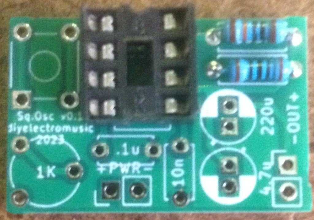
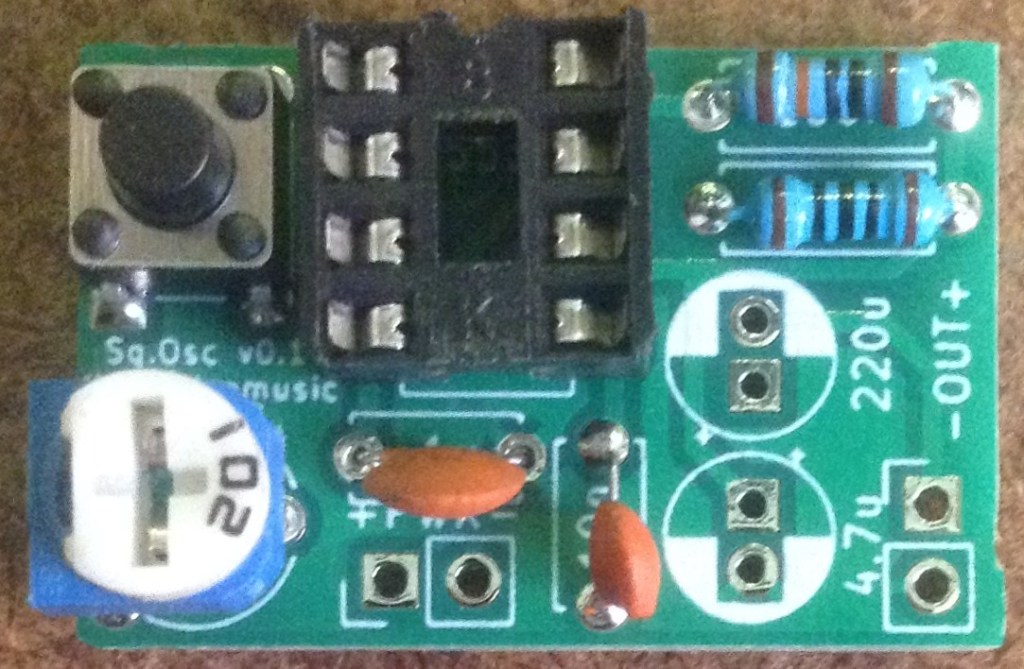
As mentioned in the design notes, there is one patch link required to actually connect the button switch to the 555 power pin (don’t ask). This is shown in the diagrams (in red) and photos below.
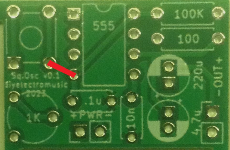
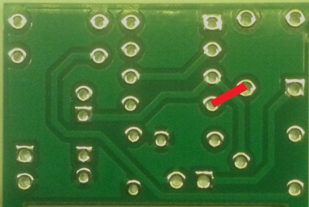
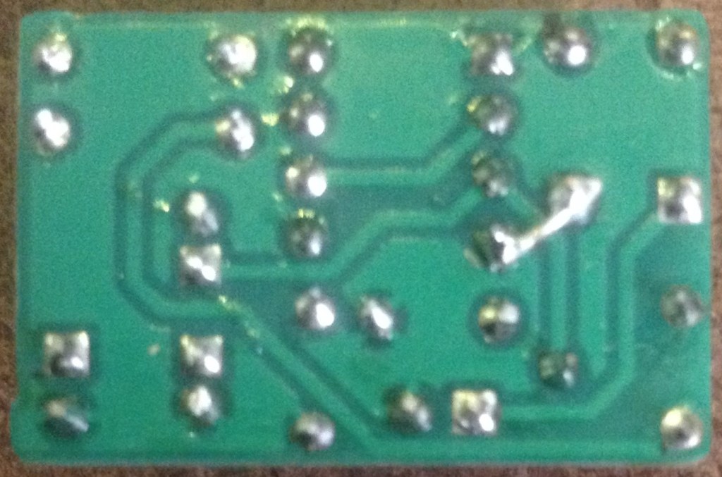
A single link on the underside is sufficient.
Testing
I recommend performing the general tests described here: PCBs.
PCB Errata
As already mentioned there is a missing link between the button switch and the 555 VCC pin.
Also, the gerber files as provided were considered as including two different designs, so may incur additional charges if used “as is”.
Closing Thoughts
The missing link is annoying, especially as I have so many of these boards now! But at least it is a very easy link to make.
I now plan to make up several of these boards and start experimenting.
These boards have been manufactured using the Seeed Fusion PCB service, which I am happy to continue to recommend. They have been supported with discount vouchers that I’ve been sent by Seeed for my previous projects.
Kevin
